Parts replacement (continued) – Nexen F-450 802700 User Manual
Page 11
11
FORM NO. L-20003-AA-1112
10. Press the old Ball Bearing(s) (Item 15 or 23) out of the
Sheave (Item 16) or Drive Disc (Item 22).
11. Clean the bearing bore of the Sheave (Item 16) or Drive
Disc (Item 22) with fresh safety solvent, making sure
all old Loctite
®
residue is removed.
12. Apply an adequate amount of Loctite
®
680 to evenly
coat the outer race of the new Ball Bearing(s) (Item
15 or 23); then, press the new Ball Bearing(s) into the
Sheave (Item 16) or Drive Disc (Item 22).
13. Reinstall the Retaining Ring (Item 36).
NOTE: The Machine Screws are installed with an
anaerobic thread locking compound. Inserting a properly
fitting screwdriver into the head of the Machine Screw
and striking the end of the screwdriver with a hammer will
break the crystalline structure of this locking compound
and allow removal of the Machine Screws. Never use
an impact wrench to remove the Machine Screws.
14. Remove the old Machine Screws (Item 13) and Friction
Facing (Item 12).
15. Install the new Friction Facing (Item 12) and secure it
with the new Machine Screws (Item 13).
16. Tighten the new Machine Screws (Item 13) to the
recommended torque (See Table 9).
17. Support the inner race of the new Ball Bearing (Item
15 or 23); then press the Hub (Item 1) into the new
Ball Bearing and Sheave (Item 16) or Drive Disc (Item
22).
18. Slide the Compression Spring (Item 14) onto the Hub
(Item 1).
NOTE: The FW Clutch has a Key (Item 20) in the Hub
(Item 1). Do not remove this Key.
The FW Clutch does not have a Fiber Washer (Item
10).
19. Lubricate the Hub (Item 1) spline with a thin coating
of Never-Seez
®
; then, slide the Friction Disc (Item 11)
onto the Hub.
20. Slide the new Fiber Washer (Item 10) onto the Hub
(Item 1).
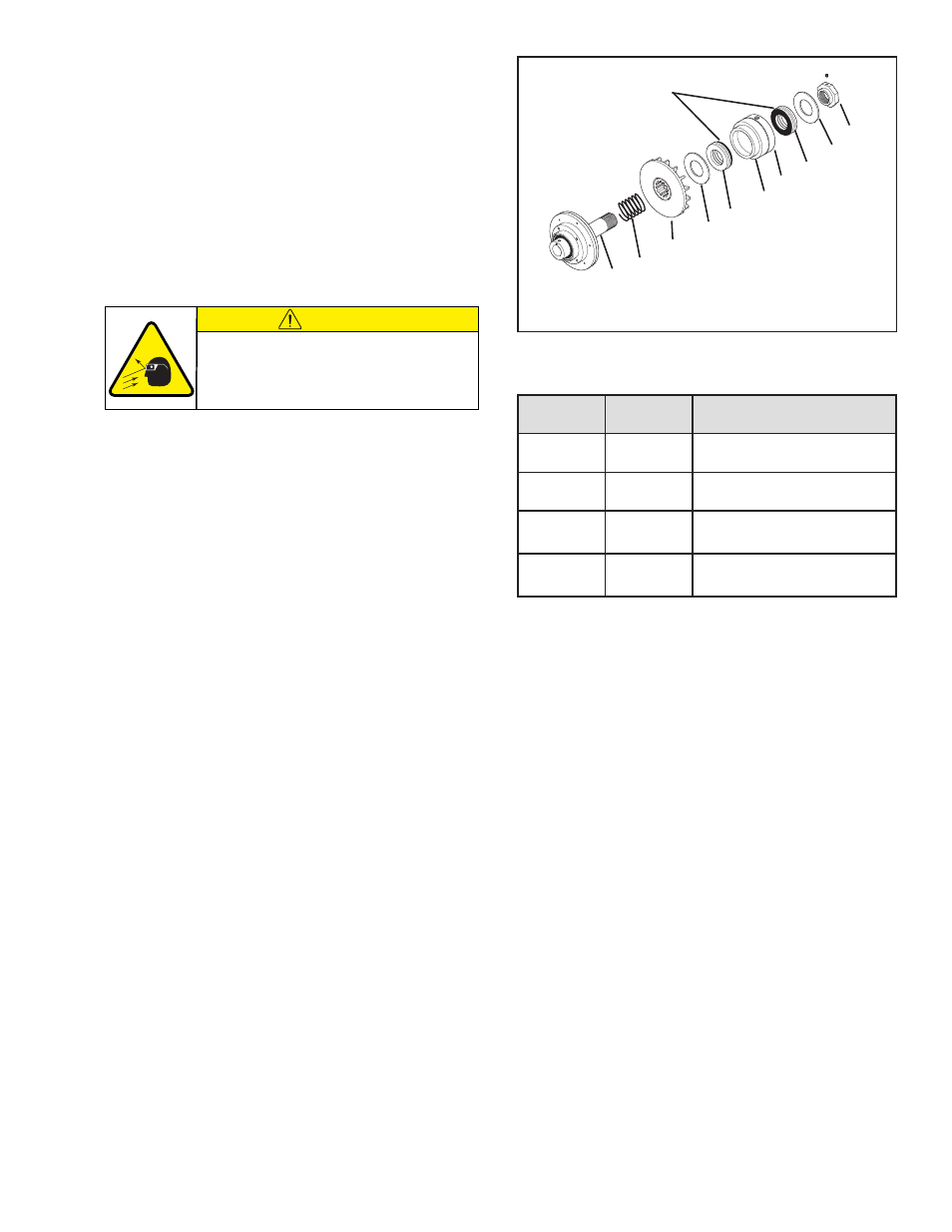
FIGURE 10
1
14
11
10
5
8
4
5
3
2
Blackened
Race
TABLE 9
RECOMMENDED TIGHTENING TORQUES
L
E
D
O
M
.
O
N
M
E
T
I
E
U
Q
R
O
T
W
F
3
1
]
m
•
N
9
.
2
[
s
b
L
.
n
I
6
2
W
L
3
1
]
m
•
N
9
.
2
[
s
b
L
.
n
I
6
2
W
M
3
1
]
m
•
N
0
.
5
-
5
.
4
[
.
s
b
L
.
n
I
5
4
-
0
4
W
H
3
1
]
m
•
N
0
.
5
-
5
.
4
[
.
s
b
L
.
n
I
5
4
-
0
4
NOTE: If Thrust Bearings (Item 5) have blackened races,
follow proper orientation procedures as indicated.
21. Slide the first new Thrust Bearing (Item 5) with the
blackened race facing the Piston/Air Chamber Assembly
into the Air Chamber (Item 8).
22. Slide the Air Chamber (Item 8) and Piston (Item 4) onto
the Hub (Item 1).
23. Slide the second new Thrust Bearing (Item 5) with the
blackened race facing the Piston/Air Chamber Assembly
into the Piston (Item 4).
24. Slide the Thrust Washer (Item 3) onto the Hub (Item
1).
25. Screw the Adjustment Nut (Item 2) onto the Hub (Item
1).
26. Adjust the gap between the Friction Facing
and the Friction Disc (See FRICTION FACING
ADJUSTMENT).
PARTS REPLACEMENT (continued)
CAUTION
Working with spring loaded or tension
loaded fasteners and devices can cause
injury. Wear safety glasses and take the
appropriate safety precautions.
- FW-450 802700 FWCB-450 802700 FCB-450 802700 LSCC-32 802700 F-450 With Metric Pilot 802799 L-600 804900 LW-600 804900 LWCB-600 804900 LCB-600 804900 LSCC-44 804900 LSCB-44 804900 L-600 With Metric Pilot 804999 H-1000 809700 HW 809700 HWCB 809700 H-1000 With Metric Pilot 809799 M-800 807400 MW-800 807400 MWCB-800 807400 MCB-800 807400 M-800 807666 M-800 807401 MW-800 807666 MW-800 807401 MWCB-800 807666 MWCB-800 807401 MCB-800 807666 MCB-800 807401 M-800 With Metric Pilot 807499 FW 846900 FW 846901 LW 847000 L-600847002 LW 847002 MW 847100 HW 847200