Replacement parts, Parts list – Nexen FMCE-130-19 801673 User Manual
Page 12
9
FORM NO. L-20306-A-0501
REPLACEMENT PARTS
The item or balloon number for all Nexen products is used
for part identification on all product parts lists, product
price lists, unit assembly drawings, bills of materials, and
instruction manuals.
When ordering replacement parts, specify model
designation, item number, part description, and quantity.
Purchase replacement parts through your local Nexen
Distributor.
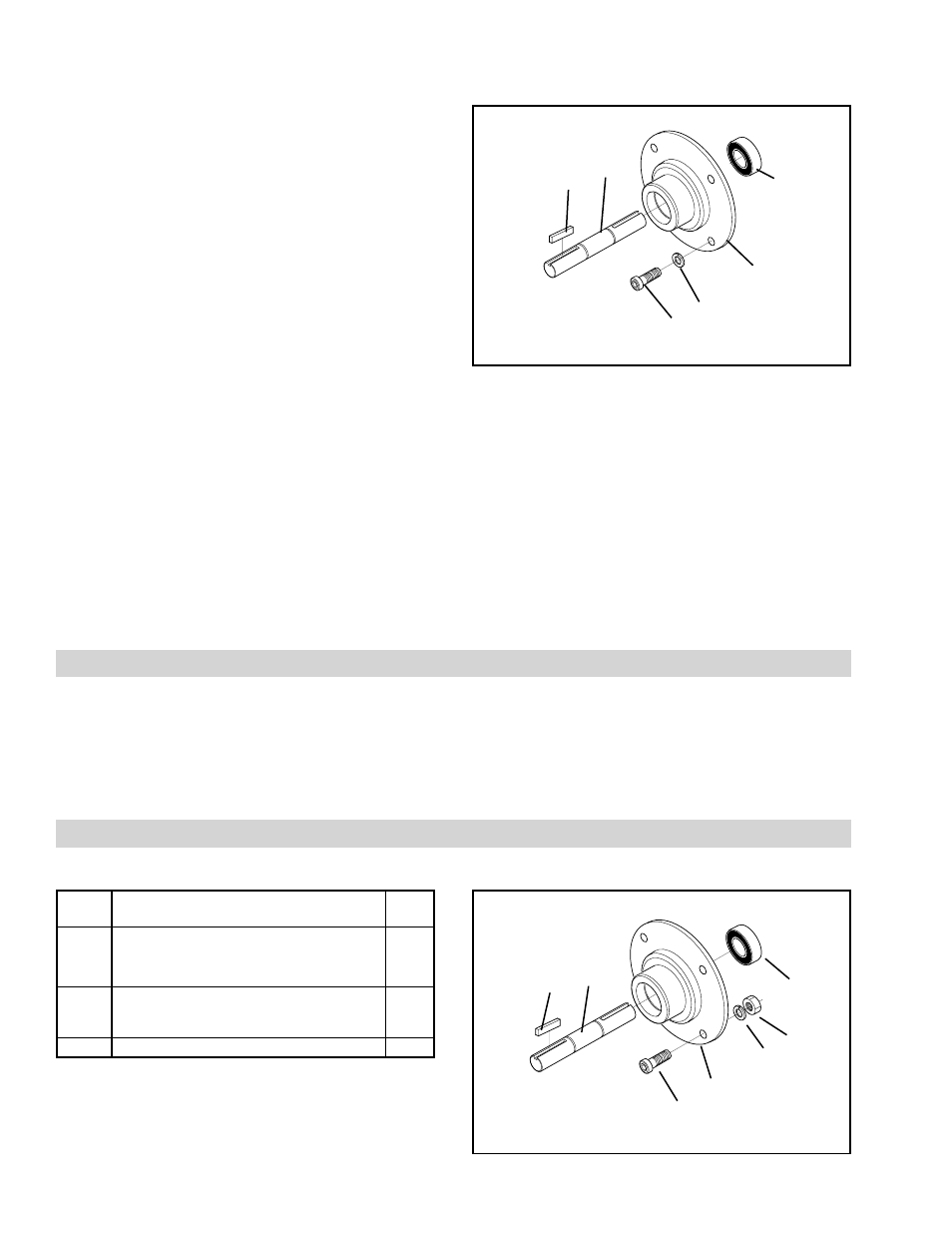
29
30
FIGURE 10
19
28
25
INPUT UNIT
NOTE: Remove the Plug (Item 32) and loosen the Set
Screw (Item 31) one full turn to release the Input
Unit shaft from the FMCE. The Plug (Item 32) is
located on the FMCE Housing and the Set
Screw (Item 31) is located in the Drive Disc.
1.
Remove the Socket Head Cap Screws (Item 29)
and Lock Washers (Item 30); then, remove the Input
Unit from the FMCE.
2.
Fully supporting the Input Unit, press the Shaft (Item
28) and Ball Bearing (Item 19) out of the Input Unit
(See Figure 10).
3.
Press the Ball Bearing (Item 19) off the Shaft (Item
28) (See Figure 10).
NOTE: Do not reuse the Ball Bearings. Applying
force to the inner bearing race to remove a
bearing held by the outer race causes
damage to the Ball Bearing.
4.
Clean the bearing bore of the Flange (Item 27) with
fresh solvent, making sure all old Loctite
Ò
residue is
removed.
27
5.
Apply an adequate amount of Loctite
Ò
680 to evenly
coat the outer race of the new Ball Bearing (Item 19)
(See Figure 10).
6.
Carefully align the outer race of the new Ball Bearing
(Item 19) with the bore of the Flange (Item 27) and
press the Ball Bearing into the Flange until it is
seated (Item 24) (See Figure 10).
7.
While supporting the inner race of the Ball Bearing
(Item 19), press the Input Shaft (Item 28) into the
Ball Bearing and Flange (Item 27).
PARTS LIST
INPUT UNIT
ITEM
DESCRIPTION
QTY
19
1
Ball Bearing
1
25
Key
2
27
Flange
1
28
Shaft
1
29
Socket Head Cap Screw
4
30
Lock Washer
4
31
Hex. Nut
4
1
Denotes Input Unit Repair Kit item / Repair Kit No. 801429.
FIGURE 11
27
29
30
31
19
25
28