Nexen FMCE-130-19 801673 User Manual
Page 11
8
FORM NO. L-20306-A-0501
23
20
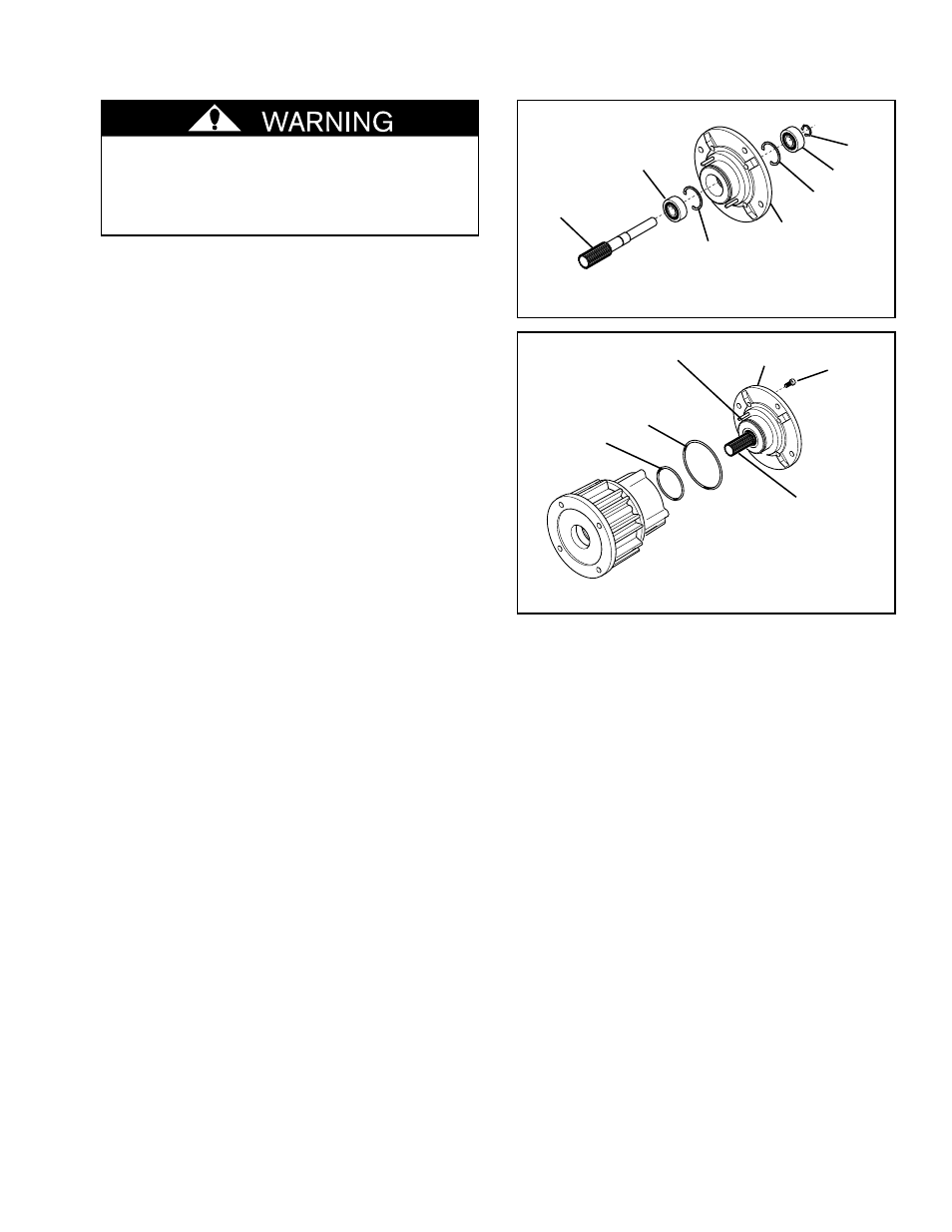
FIGURE 8
19
18
18
19
24
Special attention should be exercised when
working with retaining rings. Always wear
safety goggles when working with spring or
tension loaded fasteners or devices.
1.
Remove the Retaining Ring (Item 24) from the Stub
Shaft (Item 23) (See Figure 8).
2.
Press the Stub Shaft (Item 23) out of the Male Pilot
(Item 20) (See Figure 8).
NOTE: One old Ball Bearing (Item 19) will remain
attached to the Stub Shaft (Item 23) (See
Figure 8).
3.
Press the old Ball Bearing from the Stub Shaft (Item
23) (See Figure 8).
4.
Press the other old Ball Bearing out of the Male Pilot
(Item 20) (See Figure 8).
NOTE: It is not necessary to remove the Retaining
Rings (Item 18) from the inside of the Male
Pilot.
5.
Clean the bearing bore of the Male Pilot with fresh
solvent, making sure all old Loctite
®
residue is
removed.
6.
Apply an adequate amount of Loctite
®
680 to evenly
coat the outer race of one new Ball Bearing.
7.
Carefully align the outer race of the first new Ball
Bearing (Item 19) with the bore of the output side of
the Male Pilot. While supporting the Male Pilot and
pressing on the outer race, press the new Ball
Bearing until it is seated against the Retaining Ring
inside the Male Pilot (See Figure 8).
8.
Press the second new Ball Bearing onto the Stub
Shaft (Item 23) (See Figure 8).
9.
Apply an adequate amount of Loctite
®
680 to evenly
coat the outer race of the second new Ball Bearing.
10. Carefully align the outer race of the new Ball Bearing
with the bore of the Male Pilot.
11. While pressing on the outer race of this Ball Bearing
and supporting the inner race of the new Ball Bearing
already in the Male Pilot, press the new Ball Bearing
and Stub Shaft into the Male Pilot until it is seated
against the Retaining Ring inside Male Pilot (See
Figure 8).
MALE PILOT BALL BEARINGS AND O-RING SEALS
Apply a thin film of
NEVER-SEEZ
®
to
the spline of the Stub
Shaft (Item 23).
Align the Slotted
Spring Pin with the
hole in the Piston.
20
FIGURE 9
22
21
13
12. Reinstall the Retaining Ring (Item 24) (See Figure 8).
13. Coat the O-ring contact surfaces of the Male Pilot,
Piston, and the new O-ring Seals (Items 21 and 22)
with a thin film of fresh O-ring lubricant.
14. Install the new O-ring Seals onto the Male Pilot (See
Figure 9).
15. Apply a thin film of NEVER-SEEZ
®
to the spline of the
Stub Shaft (Item 23) (See Figure 9).
16. Align the Slotted Spring Pin on the Male Pilot with
the hole in the Piston.
17. Slide the Male Pilot and Stub Shaft into the FMCE
(See Figure 9).
18. Apply a drop of Loctite
®
242 to the threads of the
four Socket Head Cap Screws (Item 13).
19. Reinstall the four Socket Head Cap Screws (Item
13), securing the Male Pilot (Item 20) to the Air
Chamber (Item 12) (See Figure 9).
20. Tighten the four Socket Head Cap Screws (Item 13)
to 24.5 Ft. Lbs. [33.2 N•m] torque.