Nexen FMCBES-8-42 801481 User Manual
Page 15
15
FORM NO. L-20241-G-1209
FMCBES 110-14
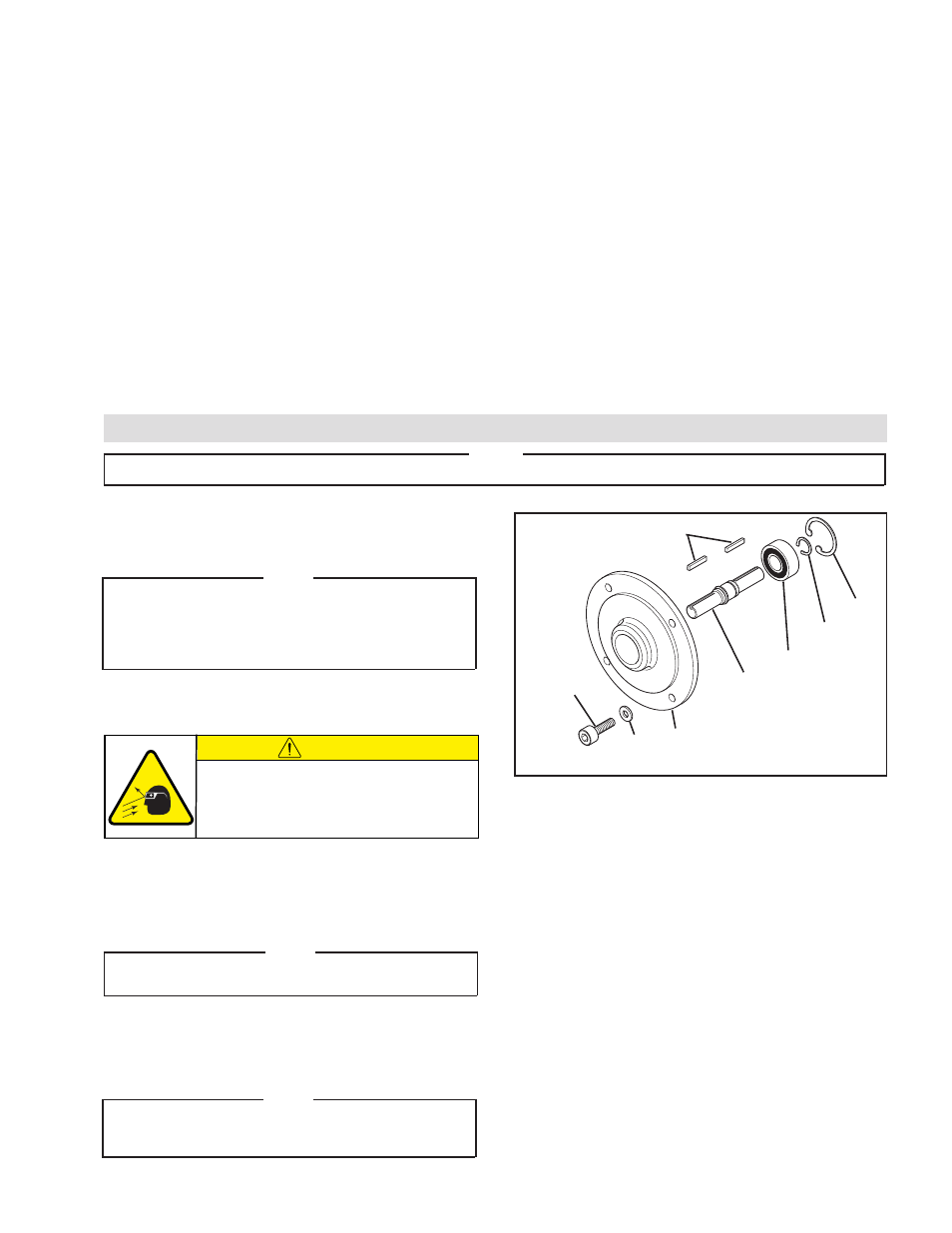
Refer to Figure 14.
NOTE
Remove the Plug (Item 35) and loosen the Set Screw
(Item 34) one full turn to release the Input Unit shaft
from the FMCBES. Both the Plug (Item 35) and Set
Screw (Item 34) are located on the FMCBES Housing
(See Figure 4).
1. Remove the Socket Head Cap Screws (Item 29) and
Lock Washers (Item 30); then, remove the Input Unit
from the FMCBES.
2. Remove the Retaining Ring (Item 34) from the output
end of the Input Unit.
3. Fully supporting the Flange (Item 27), press the Shaft
(Item 28) out of Input Unit.
NOTE
Bearing (Item 19) will come out of the Flange (Item
27) with the Shaft (Item 28).
4. Remove the Retaining Ring (Item 35) from the Shaft
(Item 28).
5. Press the old Bearing (Item 19) off the Shaft (Item
28).
NOTE
Do not reuse the old Bearing (Item 19). Applying force
to the inner bearing race to remove a bearing held by
the outer race causes damage to the bearing.
15. While supporting the inner race of Bearing (Item 29)
and pressing on the outer race of the Bearing (Item
30), press the new Bearing and Stub Shaft into the
Male Pilot and Bearing.
16. Reinstall the Retaining Ring (Item 32).
17. Coat the O-Ring contact surface of the Male Pilot,
Piston, and the new O-Ring Seals with a thin film of
fresh O-Ring lubricant and install the new O-Ring
Seals (Items 22 and 24) onto the Male Pilot.
18. Apply a thin film of NEVER-SEEZ
®
to the spline of the
Stub Shaft (Item 23).
19. Align the Slotted Spring Pin on the Male Pilot with the
hole in the Piston.
20. Slide the Male Pilot and Stub Shaft into the FMCBES.
21. Apply a drop of Loctite 242 to the threads of the four
Socket Head Cap Screws (Item 14).
22. Reinstall the four Socket Head Cap Screws (Item 14),
securing the Male Pilot (Item 18) to the Air Chamber
(Item 13).
23. Tighten the four Socket Head Cap Screws (Item 14)
to 24.5 Ft. Lbs. [33.2 N•m] torque.
PARTS REPLACEMENT –INPUT UNIT
19
28
35
34
29
30
27
FIGURE 14
25
6. Clean the bearing bore of the Flange (Item 27) with
fresh safety solvent, making sure all old Loctite®
residue is removed.
7. Apply an adequate amount of Loctite 680 to evenly
coat the outer race of the new Bearing (Item 29).
8. Carefully align the outer race of the new Bearing (Item
19) with the bore of the Flange (Item 27) and press
the new Bearing into place.
9. Reinstall Retaining Ring (Item 34).
10. Fully supporting the inner race of the Bearing
(Item 19), press the Shaft (Item 28) into the Bearing
until the Retaining Ring (Item 35) on the Shaft is
seated against Bearing.
11. Reinstall the second Retaining Ring (Item 35).
PARTS REPLACEMENT-FMCBES 7-38 (continued)
NOTE
The following sections are arranged by model. Verify that you are in the correct section for your model.
CAUTION
Working with spring loaded or tension
loaded fasteners and devices can cause
injury. Wear safety glasses and take the
appropriate safety precautions.
- FMCBES-8-42 801482 FMCBES-130-19 801466 FMCBES-130-19 801467 FMCBES-130-24 801469 FMCBES-130-24 801470 FMCBES-7-38 801475 FMCBES-7-38 801476 FMCB/E-625 801721 FMCBES-110-14 801451 FMCBES-110-14 801452 FMCBES-7-28 801472 FMCBES-7-28 801473 FMCBES-8-38 801478 FMCBES-8-38 801479 FMCBES-110-14 801401 FMCBES-130 801402 FMCBES-7-38 801661 FMCBES-7-28 801662 FMCBES-8-38 801664 FMCBES-8-42 801405