Nexen FMBES-875 827343 User Manual
Page 11
FORM NO. L-20323-D-0300
7
23. Using 'C' clamps, press the Friction Disc (Item 4) onto
the Piston (Item 5) (See Figure 10).
24. Apply a drop of Loctite
®
242 to the threads of the six
Socket Head Cap Screws (Item 12) (See Figure 10).
25. Install the six Socket Head Cap Screws (Item 12); then,
alternately and evenly tighten the Socket Head Cap
Screws (Item 12) to 30 In. Lbs. [3.4 N•m] torque. Remove
the 'C' clamps (See Figure 10).
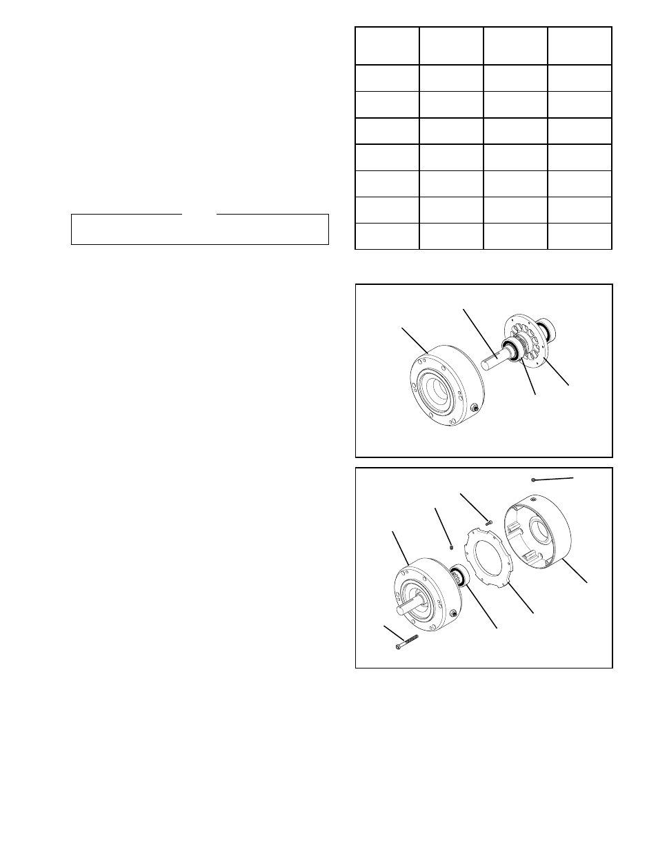
26. Carefully align the O.D. of the Ball Bearing (Item 9) with
the bore of the Housing (Item 7); then, press the Shaft
(Item 1), Ball Bearing (Item 9), and Rotor (Item 2) back
into the Housing (Item 7) (See Figure 12).
NOTE
Apply Loctite 680
®
to the outer race of the Ball Bearing
(Item 9).
27. Apply a drop of Loctite
®
242 to the threads of the six
Socket Head Cap Screws (Item 10) (See Figure 12).
28. Secure the Disc Plate (Item 8) to the Piston (Item 5)
using the six Socket Head Cap Screws (Item 10); then,
alternately and evenly tighten the six Socket Head Cap
Screws (Item 10) to 40 In. Lbs. [4.5 N•m] torque (See
Figure 12).
29. Reinstall the FMBES-CC, referring to Steps 3 through 8
of INSTALLATION (See Page 1).
L
E
D
O
M
T
C
U
D
O
R
P
.
O
N
T
U
P
T
U
O
E
U
Q
R
O
T
)
.
s
b
L
.
n
I
(
D
E
R
I
U
Q
E
R
R
E
B
M
U
N
S
G
N
I
R
P
S
F
O
C
C
-
S
E
B
M
F
5
2
6
3
2
3
7
2
8
.
s
b
L
.
n
I
0
0
1
3
C
C
-
S
E
B
M
F
5
2
6
0
2
3
7
2
8
.
s
b
L
.
n
I
0
0
2
6
C
C
-
S
E
B
M
F
5
7
8
3
4
3
7
2
8
.
s
b
L
.
n
I
0
0
1
3
C
C
-
S
E
B
M
F
5
7
8
4
4
3
7
2
8
.
s
b
L
.
n
I
0
0
2
6
C
C
-
S
E
B
M
F
5
7
8
0
4
3
7
2
8
.
s
b
L
.
n
I
0
0
3
9
C
C
-
S
E
B
M
F
5
2
1
1
0
6
3
7
2
8
.
s
b
L
.
n
I
0
0
4
9
C
C
-
S
E
B
M
F
5
7
3
1
0
8
3
7
2
8
.
s
b
L
.
n
I
0
0
9
5
1
TABLE 3
FIGURE 11
7
1
9
2
FIGURE 12
6
8
9
10
30
29
11
7