Nexen FMBES-875 827343 User Manual
Page 10
6
FORM NO. L-20323-D-0300
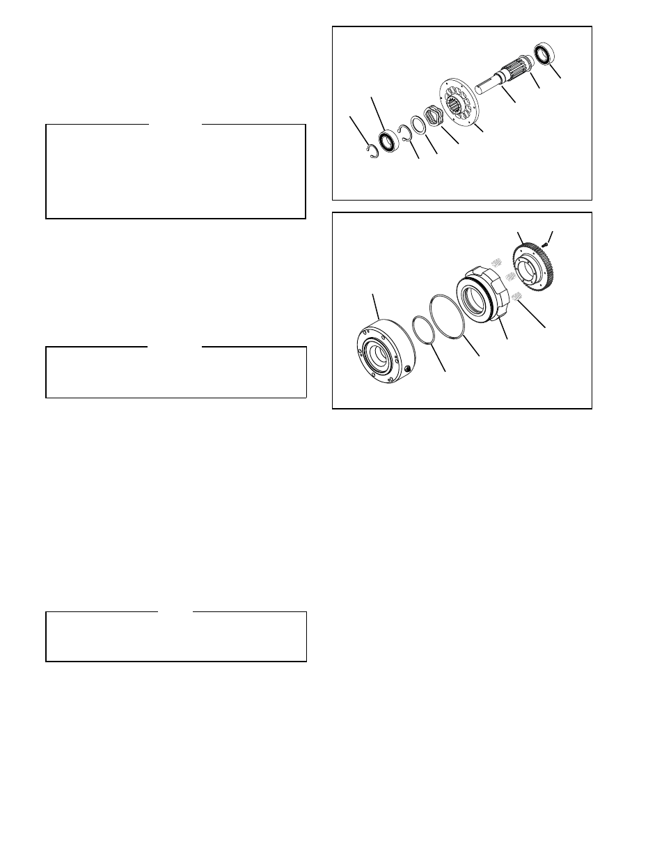
10. Reinstall the Retaining Ring (Item 15) (See Figure 9).
11. Pressing on the inner race of the two new Ball Bearings
(Item 9), press the new Ball Bearings (Item 9) onto the
Shaft (Item 1) (See Figure 10).
12. Reinstall the Retaining Ring (Item 16) (See Figure 9).
WARNING
The Friction Disc (Item 4) is spring loaded. Use 'C'
clamps to maintain pressure on the Friction Disc
(Item 4) while removing the six Socket Head Cap
Screws (Item 12). After the six Socket Head Cap
Screws have been removed, slowly release the
pressure on the 'C' clamps. Always wear safety
goggles when working on spring or tension loaded
fasteners or devices.
13. Alternately and evenly remove the six Socket Head Cap
Screws (Item 12) (See Figure 10).
14. Slowly release the pressure on the 'C' clamps; then,
remove the 'C' clamps.
15. Remove the Friction Disc (Item 4) and old Compression
Springs (Item 14) from the Piston (Item 5) (See
Figure 10).
WARNING
Do not apply excessive air pressure to slide the
Piston (Item 5) out of the Housing (Item 7). Excessive
air pressure may result in personal injury or damage
to the Piston and Housing.
16. Gently apply air pressure to slide the Piston (Item 5) out
of the Housing (Item 7) (See Figure 10).
17. Remove the old O-ring Seals (Items 20 and 21) from
the Piston (Item 5) (See Figure 10).
18. Clean the o-ring grooves of the Piston (Item 5) and o-
ring contact surfaces of the Housing (Item 7) with fresh
safety solvent (See Figure 10).
19. Lubricate the new O-ring Seals (Items 20 and 21) with
fresh o-ring lubricant; then, install the new O-ring Seals
into the Piston (Item 5) (See Figure 10).
20. Slide the Piston (Item 5) and new O-ring Seals (Items
20 and 21) into the Housing (Item 7) (See Figure 10).
NOTE
Repair Kit No. 827301 contains nine Compression
Springs (Item 14). Refer to Table 3 for the correct
number of Compression Springs required for your
Model FMBES-CC and the required output torque.
21. Install the new Compression Springs (Item 14) into the
Piston (Item 5) (See Figure 10).
22. Place the Friction Disc (Item 4) on the Piston (Item 5)
and Compression Springs (14); aligning the holes in
the Friction Disc with the tapped holes in the Housing
(See Figure 10).
FIGURE 9
9
18
9
16
17
2
1
15
15
FIGURE 10
12
4
14
5
21
20
7