Nexen SSE-1000 822530 User Manual
Page 8
8
FORM NO. L-20175-J-1112
OPERATION
The SSE Brake will remain engaged until sufficient air
pressure is applied to release it. Depending upon the
length of the air lines and the type of controls used, the
amount of release air may vary.
Apply increasing amounts of air pressure to the brake
until the Friction Disc Hub turns freely.
TABLE 4
Model
Cap Screw Size
SSE-450
10-24 x 1-1/2
SSE-600
5/16-18 x 1-3/4
SSE-800
3/8-16 x 2
SSE-1000
3/8-16 x 2-1/4
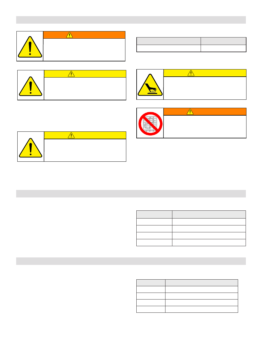
WARNING
Never exceed maximum operating
speeds listed for your product.
(See Table 3).
CAUTION
The temperature limits for this
product line are 4.5-104 Degree
Celsius (40-220 Degree F).
CAUTION
Never exceed life of facing material. Facing
life depends on the volume of material and
the total energy over the life of the unit.
Expected life (in hrs) can be found by:
Time=Volume/(Power*Wear Rate).
TABLE 3
Sizes:
Max RPM
SSE 450-1000
*1800
*Consult Nexen for high speed applications.
WARNING
Ensure proper guarding of the product is
used. Nexen recommends the machine builder
design guarding in compliance with OSHA 29
CFR 1910 “Occupational Safety and Health
Hazards”.
CAUTION
Do not use more air pressure than
required to release the brake (100
psi maximum).
MAINTENANCE
Periodically inspect all mounting bolts and air line fittings
to make sure they are securely tightened. Pay particular
attention to Shoulder Screws or Socket Head Cap Screws
(Item 6). If these screws are loose, the Cylinder (Item 10)
travel will increase, causing the O-Ring Seals to leak air.
Tighten the Shoulder Screws or Socket Head Cap Screws
(Item 6) to the recommended torque (See Table 5).
Inspect Friction Facings (Item 5) for signs of wear and
replace if worn down to where the Machine Screws (Item
14) may score the Friction Disc Hub.
TABLE 5
Model
Tightening Torques
SSE-450
48 In. Lbs. [5.0 Nm]
SSE-600
230.0 In. Lbs. [26 Nm]
SSE-800
450.0 In. Lbs. [50.8 Nm]
SSE-1000
388.0 In. Lbs. [43.8 Nm]
1. To manually release the SSE Brake, remove the three
Shoulder or Socket Head Cap Screws (Item 6) and
replace them with customer supplied cap screws (See
Table 4).
2. Tighten the cap screws alternately and evenly to draw
the Plate (Item 3) and Friction Facing (Item 5) away
from the Friction Disc Hub (Item 1).
MANUAL DISENGAGEMENT
- SSE-450 818830 SSE-450 818829 SSE-450 818865 SSE-450 818866 SSE-600 820332 SSE-600 820366 SSE-600 820330 SSE-600 820334 SSE-600 820365 SSE-800 822431 SSE-800 822430 SSE-800 822465 SSE-800 822468 SSE-800 822432 SSE-800 822466 SSE-1000 822565 SSE-1000 822572 SSE-1000 822584 SSE-1000 822566 SSE-1000 822573