Nexen 5H45PSE 910225 User Manual
Page 6
6
FORM NO. L-20255-E-0213
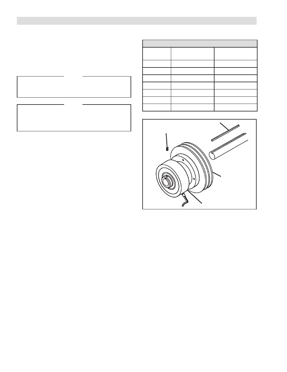
REFER TO FIGURE 1.
1. Install coupling adapter or bearing supported sprocket,
sheave, or gear onto the clutch pilot (See Table 1).
2. Insert customer supplied key into shaft.
NOTE
Nexen Spring Engaged Multiposition Tooth
Clutches mount on a full shaft using a full
length key.
NOTE
Whenever possible, arrange the input drive
to the Tooth Clutch through the drive flange
to prevent the Tooth Clutch bearings from
rotating unnecessarily.
3. Using Set Screws, secure the Tooth Clutch to the shaft.
4. Tighten Set Screws.
In severe applications, the Tooth Clutch may tend to move
axially along the shaft. To prevent this movement, confine
the Tooth Clutch between shoulders.
INSTALLATION
FIGURE 1
Set Screw
Customer Supplied Key
Bearing supported
pulley, sprocket, or
coupling
Tooth Clutch
TIGHTENING TORQUE
(with Loctite® 242)
Size
Grade 8 Socket
Head Cap Screws
Grade 8 Hex.
Head Cap Screws
#10
5 ft-lbs
6 ft-lbs
1/4 - 20
6 ft-lbs
9 ft-lbs
5/16 - 18
20 ft-lbs
18 ft-lbs
3/8 - 16
36 ft-lbs
35 ft-lbs
1/2 - 13
108 ft-lbs
114 ft-lbs
5/8 - 11
211 ft-lbs
223 ft-lbs
3/4 - 10
367 ft-lbs
400 ft-lbs
TABLE 1
- 5H45PSE 910224 5H45PSE-E 910204 5H45PSE 910226 5H60PSE-E 910410 5H60PSE-E 910424 5H35PSE 910093 5H30-SE 906701 5H30P-SE 906708 5H35PSE 910091 5H35-SE 910098 5H35-SE 910097 5H50PSE 910325 5H50-SE 907106 5H50PSE 910321 5H50PSE 910304 5H60PSE 910407 5H50-SE 907101 5H50PSE 910323 5H60PSE 910432 5H60PSE 910404 5H60-SE 910408 5H60PSE 910446 5H80PSE-E 913172 5H35SE 910122 5H35SE 910089 5H35PSE 910094 5H35SE 910121 5H50PSE 910326 5H60PSE 910419 5H60PSP-SE 910440