Nexen 5H45PSE 910225 User Manual
Page 12
12
FORM NO. L-20255-E-0213
5H-SE, PILOT MOUNT (continued)
REFER TO FIGURES 7-9.
14. Making sure not to damage the new O-rings Seals
(Items 12 and 13), press the Piston (Item 3) into the
Cylinder (Item 2).
15. Press the Drive Ring (Item 4) into the new Ball Bearing
(Item 8) and Cylinder (Item 2).
16. Install Die Springs (Item 22) into the Spring Housing
(Item 20) sockets.
17. Position the Spring Housing over the Cylinder/Piston
assembly, align the clearance holes with the tapped
holes in the Cylinder.
18 Insert Cap Screws (Item 23) into the Spring Housing and
tighten alternately and evenly until the Spring Housing
is flush with the Cylinder. Torque the Cap Screws to
the values shown in Table 4.
19. Remove the Retaining Ring (Item 11).
20. Press Hub (Item 1) out of the Drive Flange (Item 5).
NOTE
Do not remove the Backing Plate (Item 6)
from the Hub (Item 1) (See Figure 8).
21. Remove the Retaining Ring (Item 10) from the Drive
Flange (Item 5).
22. Press the old Ball Bearings (Item 9) out of the Drive
Flange (Item 15).
23. Clean the bearing bore of the Drive Flange (Item 15)
with fresh safety solvent, making sure all old Loctite®
residue is removed.
24. Apply an adequate amount of Loctite® 680 to evenly
coat the outer race of the new Ball Bearings (Item 9);
then, press the new Ball Bearings (Item 9) into the Drive
Flange (Item 15).
25. Reinstall the Retaining Ring (Item 11).
26. Press the Hub (Item 1) into the Drive Flange (Item
15) and new Ball Bearing (Item 9); then, reinstall the
Retaining Ring (Item 11).
27. Apply a thin coat of Never-Seez® to the teeth of the
Drive Ring (Item 4).
28. Press the Drive Flange (item 15) and Hub (Item 1) into
the Cylinder (Item 2) and Drive Ring (Item 4).
30. Reinstall the Retaining Ring (Item 11).
Model
Tightening Torque
5H30PSE
5 ft-lbs
5H35PSE
5 ft-lbs
5H45PSE
9 ft-lbs
5H50PSE
9 ft-lbs
5H60PSE
27 ft-lbs
TABLE 4
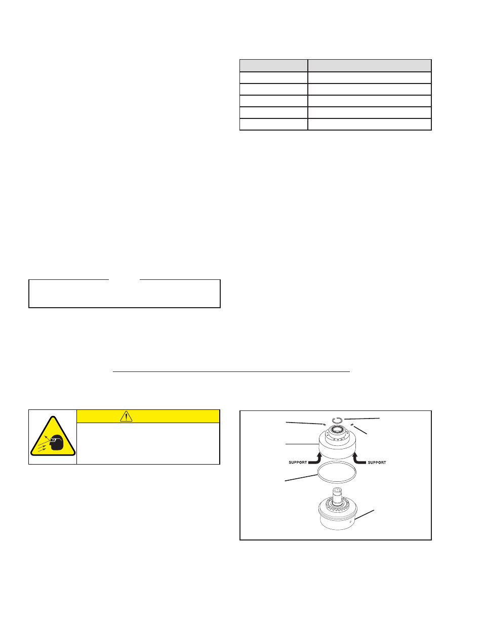
18
11
18
Hub and
Piston/Cylinder/
Spring Housing
Assembly
4
Drive
Flange
Assembly
FIGURE 10
CAUTION
Working with spring loaded or tension
loaded fasteners and devices can cause
injury. Wear safety glasses and take the
appropriate safety precautions.
5HP-SE-E, PILOT MOUNT, ENCLOSED
REFER TO FIGURE 10.
1. Remove the Set Screws (Item 18).
2. Remove the Retaining Ring (Item 11).
3. Fully supporting the lip of Drive Flange Assembly press
the Hub (Item 1) and Piston/Cylinder/Spring Housing
Assembly out of the Drive Flange Assembly.
4. Remove the old Rotary Seal (Item 4).
- 5H45PSE 910224 5H45PSE-E 910204 5H45PSE 910226 5H60PSE-E 910410 5H60PSE-E 910424 5H35PSE 910093 5H30-SE 906701 5H30P-SE 906708 5H35PSE 910091 5H35-SE 910098 5H35-SE 910097 5H50PSE 910325 5H50-SE 907106 5H50PSE 910321 5H50PSE 910304 5H60PSE 910407 5H50-SE 907101 5H50PSE 910323 5H60PSE 910432 5H60PSE 910404 5H60-SE 910408 5H60PSE 910446 5H80PSE-E 913172 5H35SE 910122 5H35SE 910089 5H35PSE 910094 5H35SE 910121 5H50PSE 910326 5H60PSE 910419 5H60PSP-SE 910440