Nexen 5H45PSE 910225 User Manual
Page 13
13
FORM NO. L-20255-E-0213
5HP-SE-E, PILOT MOUNT, ENCLOSED (continued)
REFER TO FIGURES 10-18.
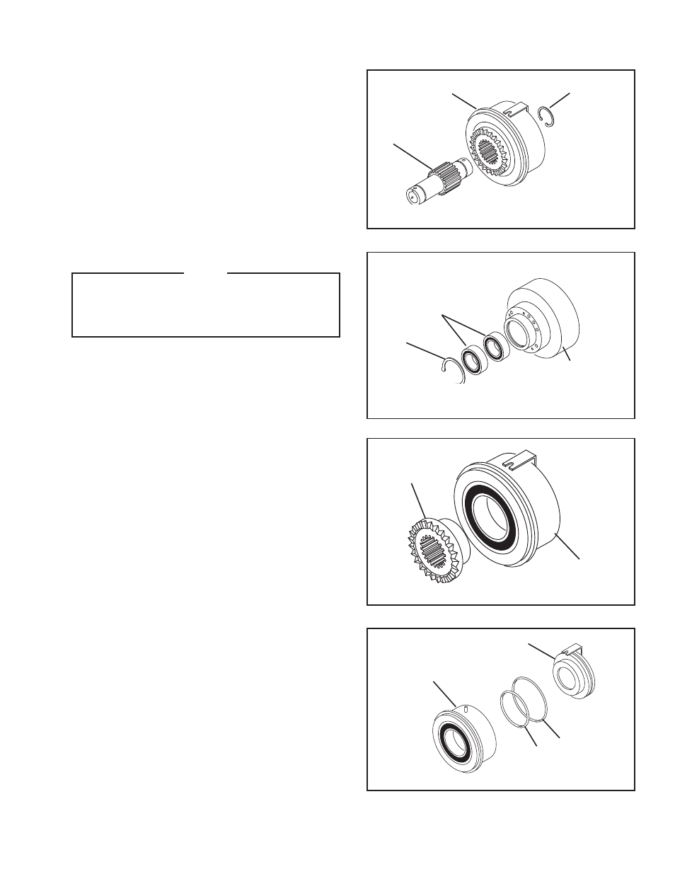
5. Remove the Retaining Ring (Item 11).
6. Fully supporting the Cylinder/Piston/Spring Housing
Assembly, press the Hub (Item 1) out of the Cylinder/
Piston Assembly.
7. Remove the Retaining Ring (Item 24).
8. Press the old Ball Bearings (Item 9) out of the D r i v e
Flange Assembly.
9. Clean bore of Drive Flange Assembly with fresh solvent
making sure all old Loctite
®
residue is removed.
NOTE
When installing new Ball Bearings, carefully
align the Ball Bearing O.D. with Drive Flange
Assembly bore to prevent Ball Bearing
misalignment.
10. Apply an adequate amount of Loctite
®
680 to evenly
coat the outer race of the new Ball Bearings (Item 9);
then, press the new Ball Bearings into the Drive Flange
Assembly.
11. Reinstall the Retaining Ring (Item 24).
12. Remove the Drive Ring (Item 4) from the Piston/Cylinder
Assembly.
13. Remove Cap Screws (Item 23) by loosening alternately
and evenly to relieve the die spring force.
14. Remove and discard original Die Springs (Item 22).
15. Separate the Piston (Item 3) from Cylinder (Item 2).
16 Remove the old O-ring Seals (Items 12 and 13) from
the Piston (Item 3) and Cylinder (Item 2).
17. Press old Ball Bearing (Item 8) out of Piston (Item 3).
18. Clean the bearing bore of the Piston (Item 3) with fresh
solvent making sure all old Loctite
®
residue is removed.
19. Apply an adequate amount of Loctite
®
680 to evenly
coat the outer race of the new Ball Bearing (Item 8);
then, press new Ball Bearing into the Piston (Item 3).
20. Reinstall the Retaining Ring (Item 11).
11
Cylinder/Piston
Assembly
1
FIGURE 11
FIGURE 12
24
9
Drive Flange
Assembly
FIGURE 13
4
Cylinder/Piston
Assembly
FIGURE 14
2
13
12
3
- 5H45PSE 910224 5H45PSE-E 910204 5H45PSE 910226 5H60PSE-E 910410 5H60PSE-E 910424 5H35PSE 910093 5H30-SE 906701 5H30P-SE 906708 5H35PSE 910091 5H35-SE 910098 5H35-SE 910097 5H50PSE 910325 5H50-SE 907106 5H50PSE 910321 5H50PSE 910304 5H60PSE 910407 5H50-SE 907101 5H50PSE 910323 5H60PSE 910432 5H60PSE 910404 5H60-SE 910408 5H60PSE 910446 5H80PSE-E 913172 5H35SE 910122 5H35SE 910089 5H35PSE 910094 5H35SE 910121 5H50PSE 910326 5H60PSE 910419 5H60PSP-SE 910440