Top front, Fr o n t, Assembly step 2 mounting the legs – Weston Outdoor Propane Vertical Smokers User Manual
Page 6: Lighting procedures, Ignitor lighting system, Match lighting, Damper adjustments, Shutting the smoker off
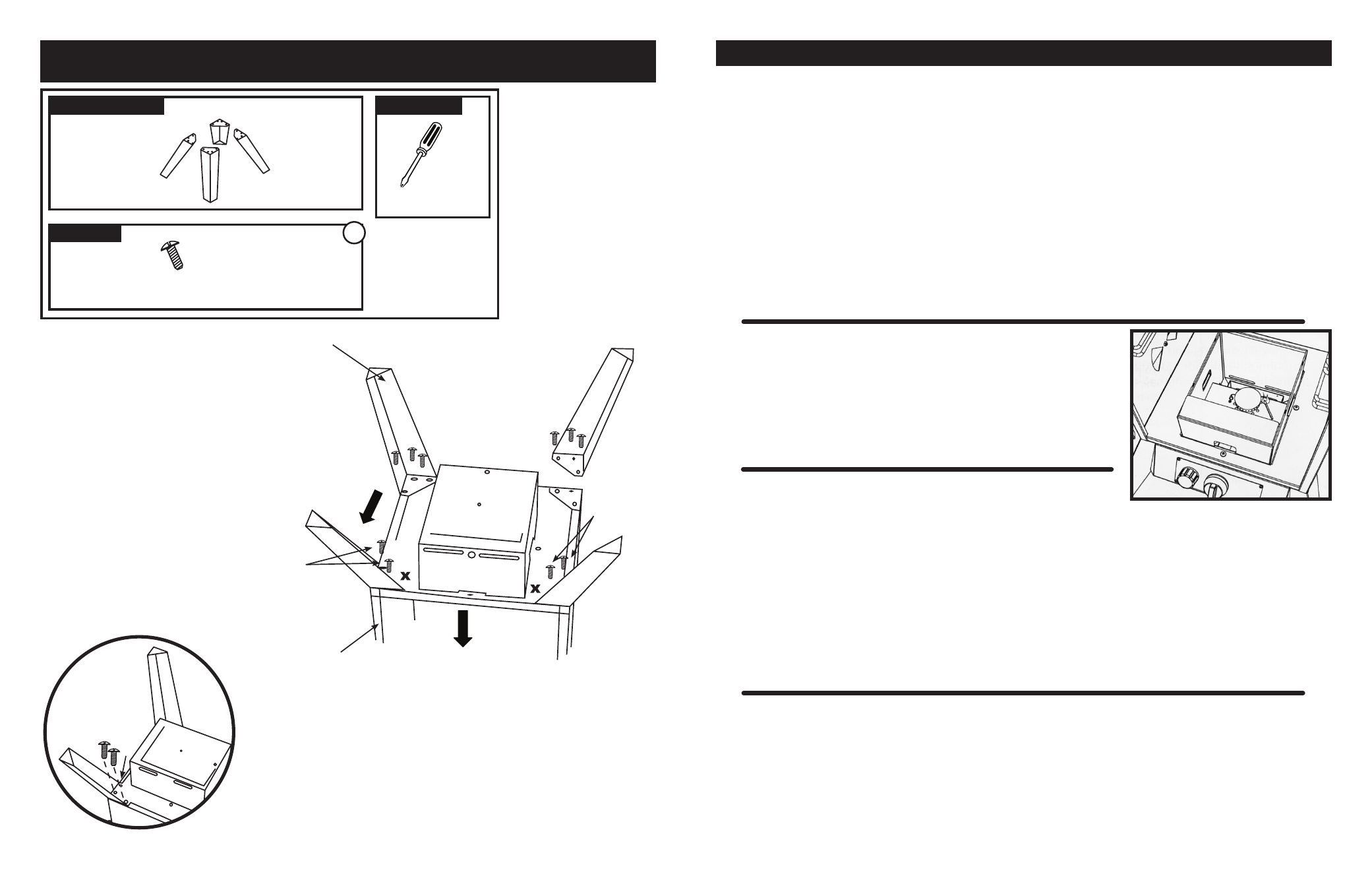
ASSEMBLY STEP 2
MOUNTING THE LEGS
A
LOCATE THESE PARTS
HARDWARE
TOOLS NEEDED
HARDWARE BAG
PHILLIPS
HEAD
SCREWDRIVER
4 LEGS
LIGHTING PROCEDURES
IGNITOR LIGHTING SYSTEM
1. Check all connections for leaks using the “soapy water” test as explained in the “CHECK FOR GAS LEAKS!” section of this manual.
2. Open the
Smoker Cabinet Door.
3. Check for any blockage to the
Venturi Tube or Burner. Remove any foreign objects or matter.
4. Be sure the burner control knob is in the “OFF” position.
5. Open the LP cylinder valve 1-1/2 turns by turning counter-clockwise
6. To light unit with the
Rotary Ignitor, push in and turn the Burner Control Knob counterclockwise to the high setting.
7. Immediately rotate the
Ignitor Knob clockwise until you hear it click several times (you should see a small spark jumping from the
end of the electrode rod to the side of the burner). If the
Burner doesn’t light within 3 to 5 seconds, turn the Burner Control Knob
“OFF” and wait five minutes before repeating the steps again. If
Burner still fails to light, try match lighting the Smoker using the
instructions noted below.
8. Once the
Burner is lit, close the Door to allow heat to accumulate. The Dampers can then be adjusted to the desired setting to
allow proper air flow and combustion.
Damper adjustment tips are listed below.
MATCH LIGHTING
1. Follow steps 1 thru 5 of the “IGNITOR LIGHTING SYSTEM” instructions above.
2. Remove the
Wood Chip Box and the Wood Chip Box Stand from inside the Smoker.
Light a paper match and drop it into the
Burner Chamber, making sure it falls next
to the brass
Burner.
FIGURE 1.
Quickly turn the
Burner Control Knob to the light
position. If the
Burner does not light within 4 to 5 seconds, turn the Burner Control
Knob off, wait 5 minutes and repeat the process.
DAMPER ADJUSTMENTS
.
For better performance, rotate the
Smoker to where the front or back of the Cabinet is facing the wind. This allows the adjustment
of the
Dampers to be more effective and accurate.
.
The
Dampers should NEVER be fully closed.
.
Opening a side
Damper allows more oxygen to be consumed by the fire, fueling the flames and causing an increase in temperature.
.
Opening the top
Damper helps to exhaust both the heat and smoke.
.
The key to effective smoking is to watch your
Heat Indicator on the Door and adjust the Dampers accordingly.
.
Temperature maintenance is best controlled by different
Damper adjustment configurations.
.
CAUTION: Keep the Dampers open a minimum of 10% at all times.
SHUTTING THE SMOKER OFF
CAUTION: The Smoker can become very hot while in use. Do not touch any portion of the Smoker except for the Door Handle and
Burner Control Knob. It may be necessary to use protective gloves.
.
Turn the
Burner Control Knob off by pushing in and rotating clockwise. The Burner flame should then go out.
.
Turn off the LP cylinder valve by turning the knob clockwise until it stops.
.
Follow all warnings and safety precautions before removing meat from smoker or preparing the unit for storage. Please see “AFTER
USE SAFETY & MAINTENANCE” for proper storage procedures and the important warnings and safeguards.
FIGURE 1
-6-
-15-
NOTE:
Hardware Bag
A includes 12 Bolts.
You will need 10 bolts
for this step. The re-
maining 2 bolts will be
used for the next step.
Leave these
Bolts loose for
the next step.
FIGURE 3
LEGS
CABINET
ASSEMBLY
TOP
FRONT
Leave these
Bolts loose for
the next step.
x
FR
O
N
T
FIGURE 4
1. Leave the
Cabinet positioned upside down.
2. Line up the back
Legs with the mounting
holes.
FIGURE 3
Insert the 3
Bolts into each
leg (the nuts are pre-welded to the
Cabinet).
3. Tighten the back
Leg Bolts securely.
2. Line up the front
Legs with the mounting
holes. Insert 2
Bolts (the nuts are pre-welded
to the
Cabinet) leaving the third mounting hole
without a
Bolt.
REPRESENTED BY AN “X” IN FIGURE 4
4. DO NOT tighten the Bolts on the front Legs.
Leave them loose enough so that the front
Legs
can move easily.