Installation steps cont – WaterFurnace Envision Low Sill User Manual
Page 12
12
ENVISION LOW SILL CONSOLE INSTALLATION MANUAL
Installation Steps cont.
Step 4: Provide Water and Condensate Drain Connections
• A two-pipe reverse return piping configuration is recommended as it equalizes the piping circuit lengths and delivers
even water flow to each unit. A direct return piping configuration may be used, but it may be difficult to achieve and
maintain proper water flow to the units.
• An air vent must be installed in the water distribution system.
• The supply and return water piping should be run through the wall or floor penetration and terminate with a ball valve.
The piping material used must comply with all local codes.
• Refer
to:
System Cleaning and Flushing procedures.
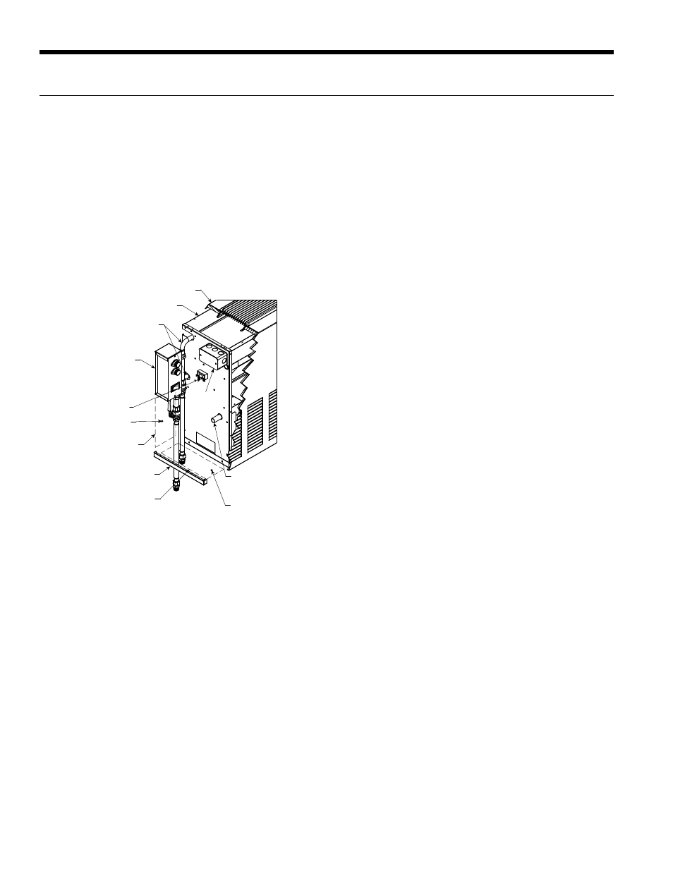
Pipe Locations
Figure 2
Condensate
Drain
Location
Water Connections
Fused Electrical
Disconnect (Optional
Wall Mounted)
Cabinet Extends
to this Point
Console Chassis
Console Cabinet
Target Area for
Wall Penetration
Target Area
for Floor
Penetration
5 in. x 8 in. Area Approx.
1/2 in. from Edge of
Chassis 1 in. from Front
Edge of Cabinet
5 in. x 8 in. Area Approx.
1/2 in. from Edge of
Chassis 3 in. from Floor
Electrical
Junction
Box
24V Accessory