Vortech 1998-2001 5.7L LS1 F-Body User Manual
Page 24
P/N: 4GK020-010
©2003 Vortech Engineering, LLC
All Rights Reserved, Intl. Copr. Secured
09JUN03 v3.2
(FBodyLS1(4GK V3.2)98-02)
12
10.
CHARGE AIR COOLER ASSEMBLY INSTALLATION, cont'd.
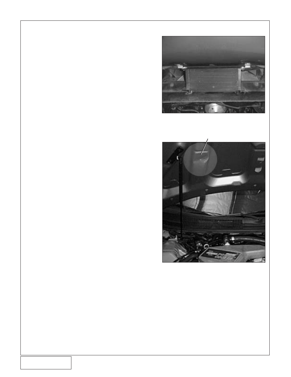
RELIEVE AS SHOWN
Fig. 10-i
Fig. 10-j
(Camaro Only)
6. Install the supplied TEE and connect the re-
maining barb on the TEE to the barb on the
surge tank using 1/4" hose.
7. Secure the hose with tie wraps.
H. Charge air cooler radiator installation
1. Remove the plastic push connectors holding
the bumper fascia on either side of the center
connector.
2. From above, install 5/16" bolts through holes
and radiator brackets and start nuts.
3. Line up and mark center line of the radiator
inlet and outlet on the air dam. With 1.25" di-
ameter hole saw, drill holes as high as pos-
sible on the air dam so that the hoses will
emerge just under the lower core support.
4. Install 90
°
fittings pointing horizontally towards
the passenger's side of the vehicle, but do not
secure the charge air cooler radiator until the
bleeding procedure is completed.
I.
Plumbing and bleeding system
1. Connect the pump discharge to charge air
cooler radiator inlet (driver’s side fitting on the
radiator).
2. Connect the charge air cooler radiator outlet
to the remaining 90
°
fitting on the charge air
cooler.
3. Allow the charge air cooler radiator to hang
with the fittings at the highest point.
4. Remove the cap from the surge tank and fill
the system with 25/75% coolant/water mix.
5. Install cap.
6. Key on power. If water isn’t circulating, turn
off the pump and check the system. (See step
16-G.)
7. Key off power.
8. Top off purge tank. (Repeat until level stabi-
lizes.)
9. Install the charge air cooler radiator as shown
and tighten mounting bolts (see
Fig. 10-i).
10. Reinstall splash panel.
J. Hood modification (
Camaro only)
1. Verify that the charge air cooler is seated on
the heat shield. The heat shield can be bent
down to further lower the charge air cooler as
long as clearance to the throttle arm is suffi-
cient.
2. Place clay or putty on the charge air cooler
and locate the area of contact with the hood.
3. Using a leather hammer, relieve the
underhood bracing until there is sufficient
clearance to the charge air cooler (see
Fig.
10-j).
4. Using clay or putty, verify clearance to the in-
let tube and MAF. Run the vehicle and check
for contact with the hood.