Supercharger mounting bracket – Vortech 1998-2001 5.7L LS1 F-Body User Manual
Page 14
P/N: 4GK020-010
©2003 Vortech Engineering, LLC
All Rights Reserved, Intl. Copr. Secured
09JUN03 v3.2
(FBodyLS1(4GK V3.2)98-02)
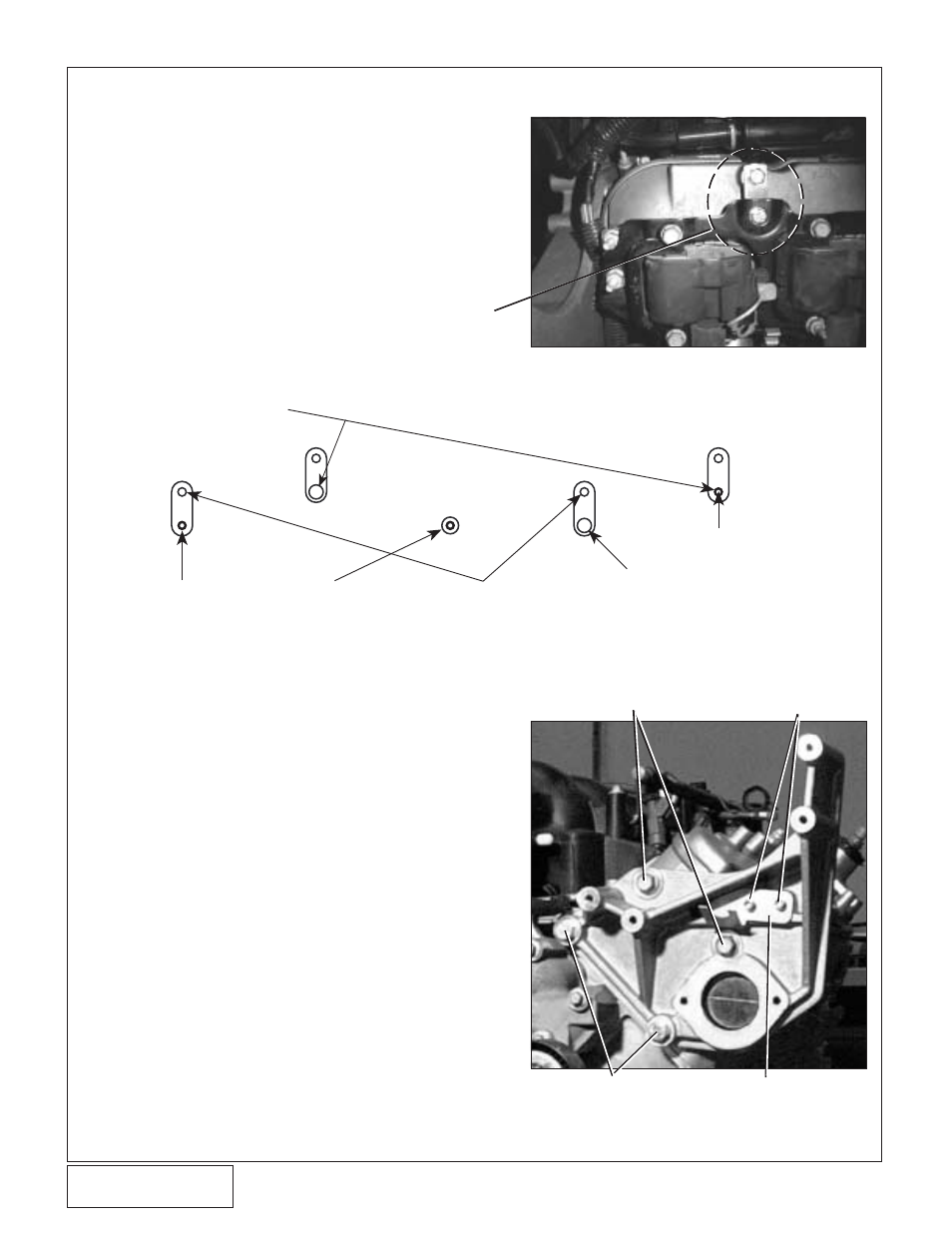
2. SUPERCHARGER MOUNTING BRACKET
A. For 1999-2002 vehicles, the driver’s side coil
mounting bracket must be relocated 1” to make
room for the supercharger inlet. Follow the
steps in the coil relocate schematic (see
Fig. 2-
a, 2-b) using the supplied 6mm hardware
unless noted. Only four of the original mounting
holes are utilized.
B. Unbolt the coil bracket from the valve cover (5
stud bolts).
C. For 2000-2002 vehicles, insert the supplied small
breather into the end of the 3/4” hose that was
originally connected to the stock air intake plenum.
D. Remove the two electrical connectors from the
throttle body. Open up the wire loom until the MAF
sensor wire has about 15” of free length (about
where the #2 injector wire joins loom). Wrap the
MAF wires with electrical tape and cover with the
supplied plastic wire loom. Wrap the remaining
plugs with electrical tape and plastic wire loom
as factory installed. Reconnect the connectors to
the throttle body.
E. Clean the front of driver's side head of debris.
F. Bolt the mounting bracket to the head with two of
the factory bolts and the two supplied 45mm long
bolts. (See
Fig. 2-c.)
G. Make sure that mounting bracket is seated directly
on the machined surface on the cylinder head
and that no wires are pinched.
H. Tighten the four mounting bolts to 37 ft/lb
(50 N·m).
VORTECH TAB INSTALLED
2
Figure: 2-a
Coil Relocation Schematic
Fig. 2-b
POWER STEERING PUMP SUPPLY
FITTING RETAINING BRACKET
Fig. 2-c
1/4-20
SOCKETHEAD CAP
SCREWS
SUPPLIED
45MM BOLTS
FACTORY POWER STEERING
BRACKET BOLTS REINSTALLED
USE FACTORY
HARDWARE
STEP 2: BOLT THESE TWO SUPPLIED
TABS LOOSELY TO COIL BRACKET
THIS VALVE COVER MOUNTING
BOSS IS NOT USED
STEP 1: BOLT TABS
TO VALVE COVER
USE FACTORY HARDWARE
STEP 4: INSTALL THE REMAINING HARDWARE INTO THE
MOUNTING TABS AND TIGHTEN ALL NUTS AND BOLTS
BEGINNING WITH THOSE MOUNTED TO VALVE COVER
STEP 3: INSTALL COIL BRACKET SO THAT
IT PILOTS IN THIS HOLE, LOOSELY INSTALL
6MM BOLT AND NUT WITH WASHERS