Charge air cooler assembly installation, cont'd – Vortech 1998-2001 5.7L LS1 F-Body User Manual
Page 21
P/N: 4GK020-010
©2003 Vortech Engineering, LLC
All Rights Reserved, Intl. Copr. Secured
09JUN03 v3.2
(FBodyLS1(4GK V3.2)98-02)
9
10.
CHARGE AIR COOLER ASSEMBLY INSTALLATION, cont'd.
Fig. 10-c
Fig. 10-d
Fig. 10-e
3. Place the #52 hose clamp over the raised tab
on the A/C canister anchor. A/C line support
clamp may need to be removed for ease of
installation. Tighten the clamp until the A/C
canister is seated tightly against its anchor.
Tighten the bolt securing the anchor to the
strut tower. Tighten the factory clamp-on A/C
canister bracket.
C. Water reservoir assembly
1. Install the 1/2” NPT 90
°
hose barb fitting into
the bottom of the supplied plastic reservoir.
Install 1/2” NPT straight barb into top reser-
voir hole.
2. If the 1" NPT on top of tank has a through
hole, install 1" NPT pipe plug.
D. Water pump wiring
1. Mount the supplied relay and #86 relay termi-
nal grounding wire on to the stud on the
driver’s side strut tower. Remove all paint and
dirt from around the mounting hole to ensure
a good ground.
2. Connect the supplied fuse, fuse holder and
large ring terminal from the #30 relay termi-
nal to the remote (+) positive battery terminal
on the fuse box.
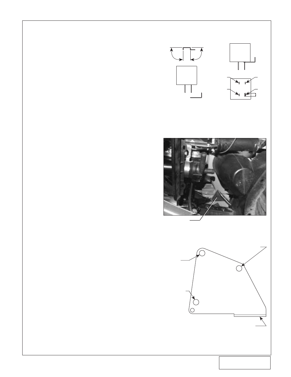
3. Open the fuse box containing the ignition re-
lay. Remove the relay. Modify and install the
mini fuse tap per diagram on the #86 terminal
of the factory relay. Reinstall the factory igni-
tion relay with the fuse tap in place. Using the
yellow wire from the #85 terminal on the
Vortech relay and a spade connector, connect
to the fuse tap. (See
Fig. 10-c.)
4. Using the supplied red wire, extend the posi-
tive (+) wire from the pump to the #87 relay
terminal.
5. Route the negative (-) wire from the pump to
a clean ground free from paint and vehicle
under coating. Use the supplied eyelet and
screw to ground the wire to the vehicle
chassis.
E. Reservoir/water pump assembly installation (see
Fig. 10-f on the following page.)
1. From area near radiator overflow tank, route
3/4" hose down past the outside of the bat-
tery. This hose will be connected to the top of
the charge air cooler reservoir.
2. Underneath the vehicle, remove the
passenger's side splash panel located in front
of the front wheel.
3. Remove the nut holding driving light support
and the bolt directly behind it. Install the
Camaro water tank bracket between driving
light support and vehicle using the original
nut and bolt (see
Fig. 10-d).
FUSE TAP
MODIFICATION
BEND UP 90
°
BEND UP 90
°
IGNITION
RELAY
MODIFIED
FUSE TAP
INSTALLED MODIFIED
FUSE TAP
BOTTOM VIEW
86
85
87
30
IGNITION
RELAY
SIDE VIEW
USE SUPPLIED
8mm BOLT IN
STOCK HORN
BRACKET
MOUNTING
LOCATION
MOUNT HORN
BRACKET
ASSEMBLY IN
THIS LOCATION
WITH SUPPLIED
8mm BOLT AND
NUT
USING THE WATER PUMP RETAINING BRACKET,
MOUNT TO THE WATER PUMP MOUNTING
BRACKET USING THE SUPPLIED 1/4”
HARDWARE ORIENTED PER PHOTO
USE SELF TAPPING 8MM HORN
BRACKET BOLT TO SECURE
BRACKET IN THIS LOCATION
WATER PUMP
MOUNTING BRACKET
INSTALLED
TANK BRACKET