Vortech 1998-2001 5.7L LS1 F-Body User Manual
Page 16
P/N: 4GK020-010
©2003 Vortech Engineering, LLC
All Rights Reserved, Intl. Copr. Secured
09JUN03 v3.2
(FBodyLS1(4GK V3.2)98-02)
4
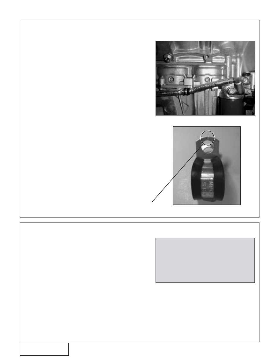
4. OIL FEED LINE
A. Spray the nuts securing the driver’s side catalytic
converter with penetrating oil and remove. Use
caution not to shear off the exhaust manifold
studs!
B. Remove the two bolts holding the small casting
located just above the oil filter.
C. Drill through the existing hole in the casting neck
with an “R” drill bit and tap 1/8” NPT. Thoroughly
clean the neck with solvent to remove metal clips.
D. Using engine oil on the threads, install the
supplied 1/8” NPT to #4 90
°
fitting so it will point
forward and away from the exhaust when
installed on the vehicle (see
Figure 4-a).
E. Reinstall the neck into its original position.
F. Temporarily cover one end of the oil feed line and
protect it from debris until connecting it to the
supercharger.
G. Connect the open end of the oil feed line to the
fitting. Install the fire sleeve on the portion of the
oil feed line that is near the exhaust and secure
both with an adel clamp. Route the line along the
oil pan rail to the front of the engine. Use an adel
clamp at the front of pan and tie wraps to secure
the line and protect it from kinking, abrasion, and
high heat areas. From the front of the pan, leave
the oil feed line loose (routing will be completed
after the supercharger is installed). The adel
clamps will need to be clipped with side cutters
to allow the bolt to pass through the hole (see
Fig. 4-b).
H. Re-install the catalytic converter.
5.
HARMONIC DAMPER INSTALLATION
A. Make sure no debris or oil is on the crank snout
or inner bore of the supplied damper.
B. Use the damper installation tool to seat the
damper on the crankshaft. (See Tool & Supply
Requirements on page v.)
C. Install per factory manual as follows:
1. Install the original retaining bolt and torque to
240 ft/lb. Remove the bolt.
2. Lightly coat the threads of the new retaining
bolt with red threadlocker. Install and torque
to 37 ft/lbs.
3. Using 1/2" breaker bar, tighten the retaining
bolt an additional 120
°
or tighten with a torque
wrench to 250 ft/lbs.
D. Use a small amount of paint or equivalent to mark
the retaining bolt and balancer hub so that any
relative movement between the two will be easy
to check after the vehicle has been operated.
Fig. 4-a
Fig. 4-b
NOTE:
It is helpful to mark the breaker bar
location on the damper under light
torque. Tighten the bolt until the
breaker bar is at the same position
under the same light torque as used
previously, but is advanced two flats
on the bolt head. This yields 120
°
of
bolt rotation.
CLIP HERE