Vortech 1996-2000 5.7L Vortec Truck/SUV User Manual
Page 15
P/N: 4GM020-010
©2000 Vortech Engineering, Inc.
All Rights Reserved, Intl. Copr. Secured
14AUG00 V 1.2
(Vortec 350-2 )4GM
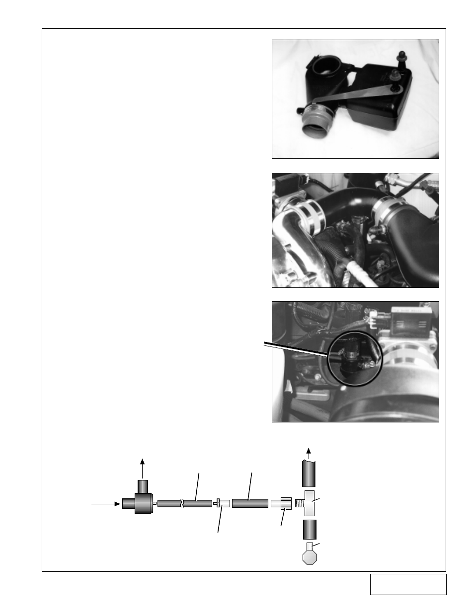
8.
SUPERCHARGER DISCHARGE
A. Following
Fig. 8-a
, attach the supplied discharge
support between the VORTEC plenum and the
throttle body duct. Sandwich the dogleg end of the
support in between the #56 hose clamp and the
reducer sleeve. Make sure that the circular end of
the support is up flush against the bottom of the
plenum.
B. Attach the discharge tube between the super-
charger and the throttle body plenum using the
supplied 3.5-2.75 reducer, 2.75 sleeve, #56 and
#52 hose clamps.
C. Following
Fig. 8-b
, connect the 1” x 6” and 1” x 3”
hoses to the supplied supercharger bypass valve
and secure with #16 hose clamps. Attach the
bypass valve/hose assembly to the bung located
on the discharge tube and the plastic 1” fitting
located on the inlet elbow (make sure that the
bypass valve nipple is pointing down when in-
stalled). (See
Fig. 8-c
.) Secure with #16 hose
clamps.
D. Remove the 1/2” brake booster vacuum line from
the intake manifold fitting and cut approximately 2"
off the end. Splice the supplied adapter TEE into
the brake booster line. Run the supplied piece of
1/4” vacuum hose from this TEE to the reducer,
and connect the 5/32" hose to the nipple located on
the bottom of the supercharger bypass valve. ( See
Fig. 8d
.)
E.
Attach the supplied 3/4" vacuum cap to the
open barb located on the factory throttle
body duct (previous crankcase vent tube
location). Secure with supplied tie wrap.
7
BYPASS
VALVE
SUPERCHARGER
AIR INLET ELBOW
5/32” HOSE
1/4” HOSE
1/2” TEE
1/4” NPT x 1/4”
FITTING
REDUCER
SUPERCHARGER
DISCHARGE TUBE
BRAKE
BOOSTER
INTAKE
MANIFOLD
FITTING
Fig. 8-a
Fig. 8-b
Fig. 8-c
Fig. 8-d