Supercharger mounting pla, Supercharger mounting plate installation – Vortech 2004-2006 Ford 5.4L 3V F-150 User Manual
Page 13
5
P/N: 4FN020-010
©2007 Vortech Engineering, LLC
All Rights Reserved, Intl. Copr. Secured
02MAR07 v2.0 Ford F-150(4FNv2.0)
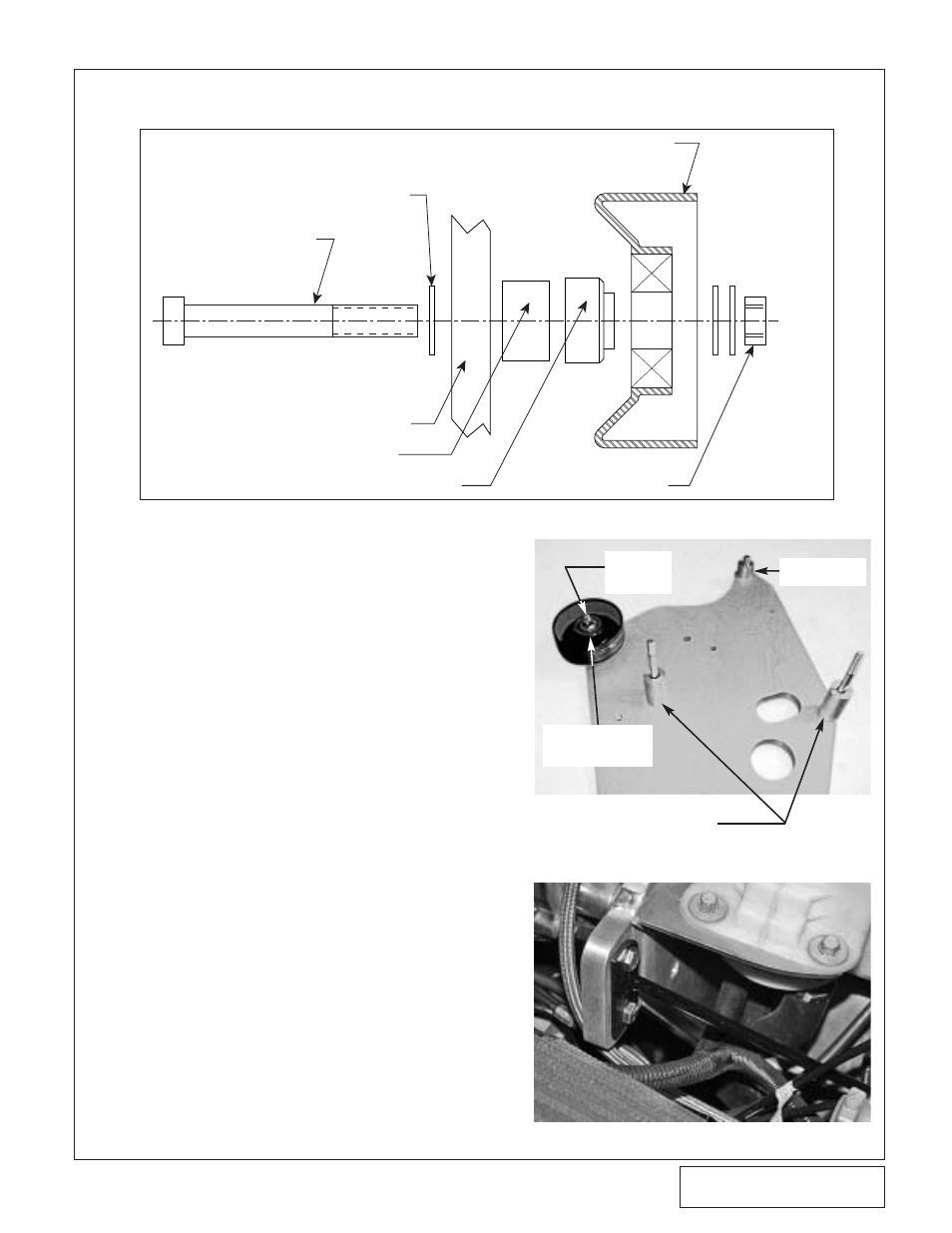
A.
Remove the smooth idler from the driver’s
side engine cover. Use one each of the sup-
plied (.55" aluminum and .46" steel with
pilot) spacers between the mounting plate
and the idler and install it on the supercharg-
er mounting plate as shown in Fig. 5-a,
using the supplied 3/8" x 2.75" bolt and nut.
B.
Route the supplied belt around the alterna-
tor and power steering pulley and loop it
over the top of the driver’s side valve cover.
C.
Install the supercharger mounting plate
using the supplied bolts and spacers. (See
Fig. 5-b.) Make sure that the belt is routed
between the alternator pulley and the
smooth idler. Make sure that the cam sen-
sor wires are not pinched. Tighten the three
bolts evenly.
D.
Loosely attach the supplied mounting plate
strut support to the two holes in the mount-
ing plate using the supplied 1/4-20 x 3/4"
bolts. Note the two exhaust manifold studs
that line up with the lower part of the strut
support and remove the nuts. Install one of
of the supplied .13" long spacers onto each
of the exhaust manifold studs. Secure the
strut support on top of the spacers by re-
installing the factory nuts. Tighten all fasten-
ers. (See Fig. 5-c.)
5.
SUPERCHARGER MOUNTING PLATE INSTALLATION
Fig. 5-b
Fig. 5-c
Fig. 5-a
M8 x 120 BOLTS 2.055"
SPACERS (COUNTER
BORED HOLES)
3/8" x 2.75" BOLT
3/8" WASHER (3x)
RELOCATED FACTORY SMOOTH IDLER
SUPERCHARGER MOUNTING PLATE
.55" ALUMINUM SPACER
.46" STEEL SPACER WITH PILOT
3/8-16 NUT
M10 x 50 BOLT
.74" SPACER
INSTALL IN
OUTERMOST
HOLE (SEE FIG. 6-b.)
3/8" x 2-1/4"
BOLT-2
WASHERS