Control features and connections, Front panel, Rear panel – Vermona DRM1 MK2 User Manual
Page 4
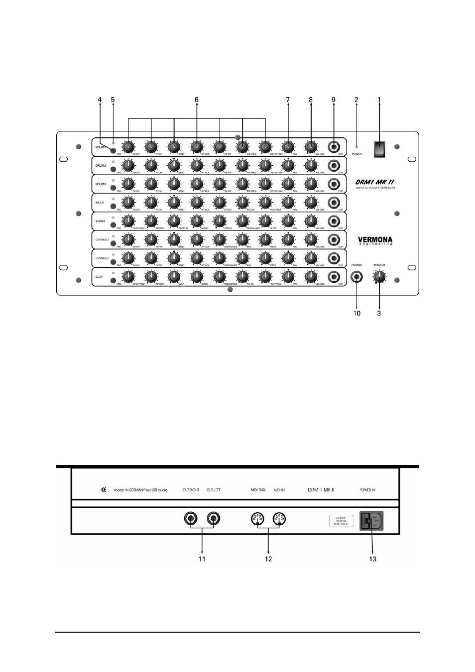
Control Features and Connections
Front Panel
1 POWER
switch
2 POWER
LED
3 MASTER:
Sets the main output level of the DRM1 MKII.
4 TRIG: Button for triggering the sound.
5 TRIG
LED: Flashes when the sound will be triggered.
6
Sound programming parameter controls
7 PAN:
Places the sound in the stereo field.
8 VOLUME: Individual volume control for each channel.
9 OUT: Individual output/insert jack.
10 PHONES: Jack for connecting a headphone.
Rear Panel
11
OUT RIGHT/OUT LEFT: Master output right and left.
12
MIDI THRU/MIDI IN: MIDI jacks for connecting a MIDI source and for putting the Midi signal through the
DRM1 MKII.
13 POWER
IN: Power jack with integrated fuse.
- Page 4 -