Appendix a: rs-232 serial overview and commands – Velodyne Digital Drive Series User Manual
Page 49
www.velodyne.com
Digital Drive Series User’s Manual - 43
APPENdIX A:
RS-232 SERIAL OVERVIEW ANd COMMANdS
Introduction
This document outlines Velodyne’s Digital Drive (DD) RS-232 protocol specification. This protocol indicates how
digital drive products receive run-time commands from devices such as creston® Universal Remote controls.
Com Port Setup
Use standard communications settings: Baud Rate: 9600, data Bits: 7, Parity: none, Stop Bits: 1
DD IN and OUT Port Pin Configuration
DD serial ports use a standard configuration that allows direct connection to a PC via a FEMALE to MALE serial
cable. It uses only 3 pins (Transmit, Receive, Ground).
The pin configurations are:
IN:
Pin 2 = Transmit
Pin 3 = Receive
Pin 5 = Ground
OUT:
Pin 2 = Receive
Pin 3 = Transmit
Pin 5 = Ground
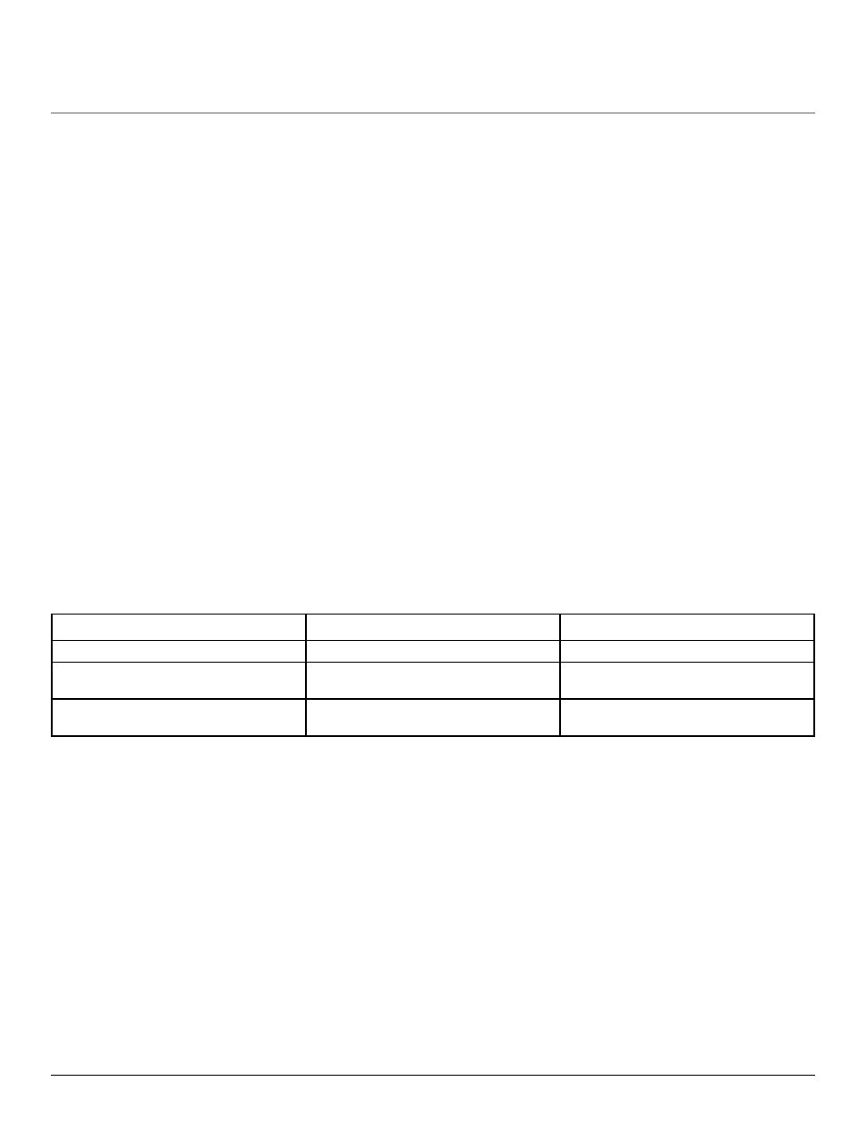
Runtime Command Format
Byte Number
Byte description
Notes
0
‘#’
Header Character
1 to 3 or 4
Command and Parameter Data
3 to 4 ASCII characters see formats below.
Case sensitive - CAPS ONLY!
4 or 5
‘$’
Termination Character (required or command is
ignored)