Iii. led indicators, Iv. remote control connections, Control inputs – SurgeX SX-20NE-RT-AR User Manual
Page 7
SX-20NE-RT-AR User Manual
Page 6
III. LED Indicators
IV. Remote Control Connections
AXESS ON
The Axess Ready system is On. The AR system must
be on to enable hard-wired remote control connections.
REMOTE
A hard-wired remote control signal is active and the
output is On.
SELF-TEST
The internal surge protection circuitry is fully functional.
Remote control connections are wired to the black 10-pin terminal block on the inside of the
unit. The terminal block is shipped with a jumper wire between pins 1 & 2 so that the unit can be
used without a remote control connection. If you will be using remote control you will first need
to remove this jumper wire. Never solder (tin) wires before inserting into a terminal block –
solder cold flows and you will eventually have loose connections!
CAUTION: Do not repeatedly turn the unit Off—On—Off—On with a heavy load
connected. The ICE™ circuitry absorbs the inrush energy each time the unit is turned on
and may overheat if this is done too many times in a short period of time. Wait one
minute between repeated turn-ons.
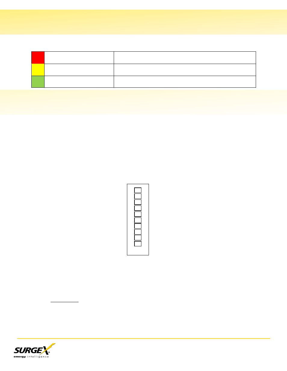
The connections are shown below:
Control Inputs
The SX-20NE-RT-AR can be controlled by a DC voltage in the range of 5V to 30V, by a contact
closure (such as a relay), by a switch (latching), or by another SurgeX product such as the SEQ.
Switches with gold contacts are recommended for the best long-term reliability.
a) DC Voltage: The unit will power up when the voltage is present, and power down when
there is no voltage. Connect the positive wire to Pin 3 (Applied Voltage +), and the
negative wire to Pin 4 (Applied Voltage -). The positive and negative connections must
be made with the correct polarity for proper operation.
Pin 1 – Contact Closure
Pin 2 – Contact Closure
Pin 3 – Applied Voltage +
Pin 4 – Applied Voltage -
Pin 5 – Power LED +
Pin 6 – Power LED -
Pin 7 – Remote LED +
Pin 8 – Remote LED -
Pin 9 – Aux Relay Contact
Pin 10 – Aux Relay Contact
1
2
3
4
5
6
7
8
9
10