Configuring the infostation ii for 4-channel – StorCase Technology Ultra160 I/O Kits User Manual
Page 8
InfoStation II Ultra160 I/O Kits
StorCase Technology, Inc.
D89-0000-0176 Rev.A00
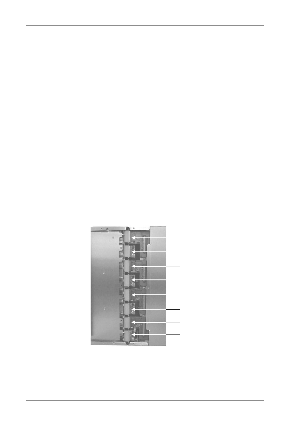
Figure 9: 4-Channel Backplane Configuration
I/O
Module
Terminator
Block
I/O
Module
Terminator
Block
Terminator
Block
IFS14_22
Terminator
Block
I/O
Module
I/O
Module
Configuring the InfoStation II for 4-Channel
CAUTION:
Remove ALL power from the InfoStation II before removing the I/O module.
The I/O module contains NO USER SERVICEABLE PARTS inside the unit.
Refer ALL servicing to qualified service personnel!
NOTE:
A #2 Phillips screwdriver will be required for this procedure.
1. Unplug the InfoStation II and verify that ALL cables have been disconnected.
2. Place the InfoStation II on a soft clean surface to protect finish of the chassis.
3. Loosen and remove the two (2) #6-32 Phillips Pan Head screws securing each I/O blank
plate to the InfoStation II chassis (Figure 6).
4. Remove all three (3) I/O blank plates.
5. Remove access panel (Figure 4).
6. Remove all the jumper blocks so that I/O modules ( #2, 3, and 4) and terminators (#2,
3, and 4) can be installed. Correct 4-channel backplane configuration is shown in
Figure 9.