Front panel – StorCase Technology 14-Bay 3U Fibre User Manual
Page 13
4
Introduction
StorCase Technology, Inc.
InfoStation 14-Bay FC User's Guide - Rev. B00
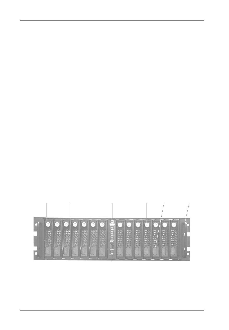
Front Panel
(Figure 2)
LED Indicator and Control Panel - LED panel displays system statuses, alarms,
and warnings. Refer to section "InfoStation User Interface" for further information.
SCA Drive Carrier(s) - Accommodate up to fourteen (14) 3.5" low-profile Fibre
Channel devices. Backplane design with direct-connect SCA connectors eliminates
cable connections to FC drives, increases data integrity, and supports drive hot
swappability.
Drive Carrier LED(s) - Provides the following information:
Drive Ready -
Indicates that the drive is properly installed and ready for
access.
Drive Activity -
Indicates that the drive is being accessed.
Drive Fault -
Indicates a drive failure.
Key Lock(s) - Assure proper seating of the drive carrier within the chassis and
prevent unauthorized removal or installation of the carrier.
NOTE:
The key lock is only to prevent unauthorized removal or installation of the
drive carrier. Locking the key lock is not requried for drive carrier oper-
ation.
Chassis Handle(s) - Provide a sturdy grip for the installation and removal of the
rack-mount chassis.
Figure 2: InfoStation Front Panel
Chassis
Handle
SCA Drive
Carrier
Drive Carrier
Handle
Key
Lock
Drive Carrier
LEDs
LED Indicator and
Control Panel
14FC_02
RS-232
Serial Port