StorCase Technology DE400 User Manual
Page 14
DE400 User's Guide - Rev. B00
StorCase Technology, Inc.
Introduction
7
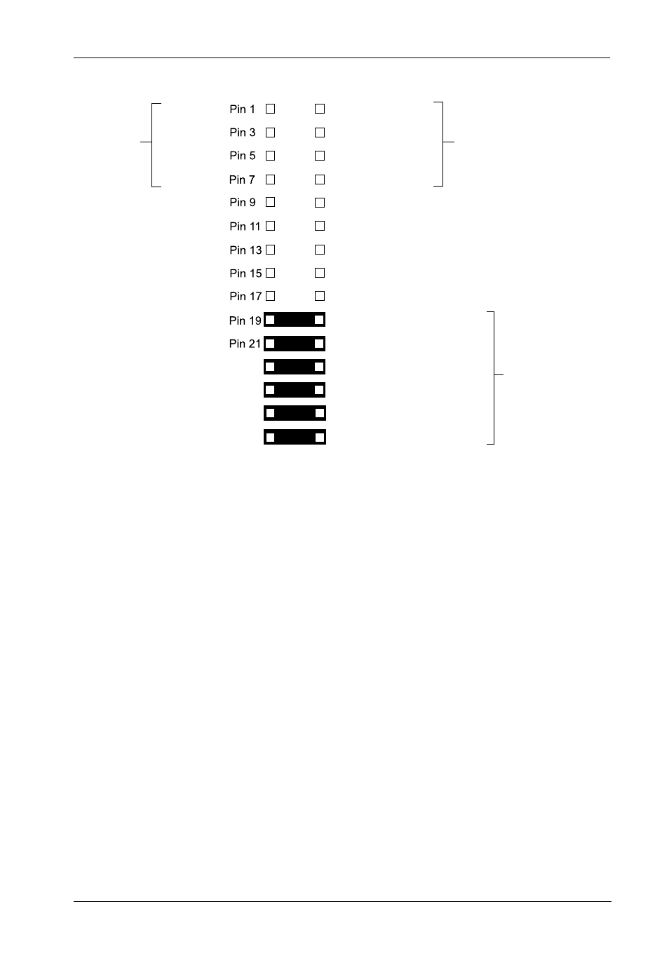
Figure 4: Option Pin Assignments
Pin 12
Pin 14
Pin 16
Pin 18
Pin 20
Pin 22
Pin 10
Pin 8
Pin 6
Pin 4
Pin 2
Bay 0
Pin 24
Pin 26
Pin 28
Pin 30
Pin 23
Pin 25
Pin 27
Pin 29
Bay 1
Bay 2
Bay 3
Bay 0
Bay 1
Bay 2
Bay 3
Remote LED
GND
Reserved
Reserved
Fan LED Enable
Fan Buzzer Enable
Reserved
Reserved
Fault
LED
Activity
LED
Factory-Installed
Jumpers
Reserved
Reserved
Reserved
Reserved
Activity LED:
Your Serial ATA host controller may provide support for the ActivityIn-
dicator feature (refer to the Serial ATA host controller manufacturer's
documentation for further information). To utilize the drive carrier Activity
LEDs, make the necessary host connection (cables not included) to Pins
1, 3, 5, & 7 (for Bays 0-3).
Fault LED:
Your Serial ATA host controller may provide support for the Fault Indicator
feature (refer to the Serial ATA host controller manufacturer's documen-
tation for further information). To utilize the drive carrier Fault LEDs, make
the necessary host connection (cables not included) to Pins 2, 4, 6, & 8
(for Bays 0-3).
Remote LED:
This provides an output signal to indicate any drive activity on Bays 0-3
(cables not included).