Drive carrier front panel – StorCase Technology DE400 User Manual
Page 11
4
Introduction
StorCase Technology, Inc.
DE400 User's Guide - Rev. B00
Drive Carrier Front Panel
(Figure 2)
Key Lock: The key lock prevents unauthorized removal or installation of the carrier.
NOTE:
The key lock is only to prevent unauthorized removal or installation of the drive
carrier. Locking the key lock is not requried for drive carrier operation.
Drive Carrier Interface Panel
:
Each drive carrier provides an interface consisting of the
following LED indicators:
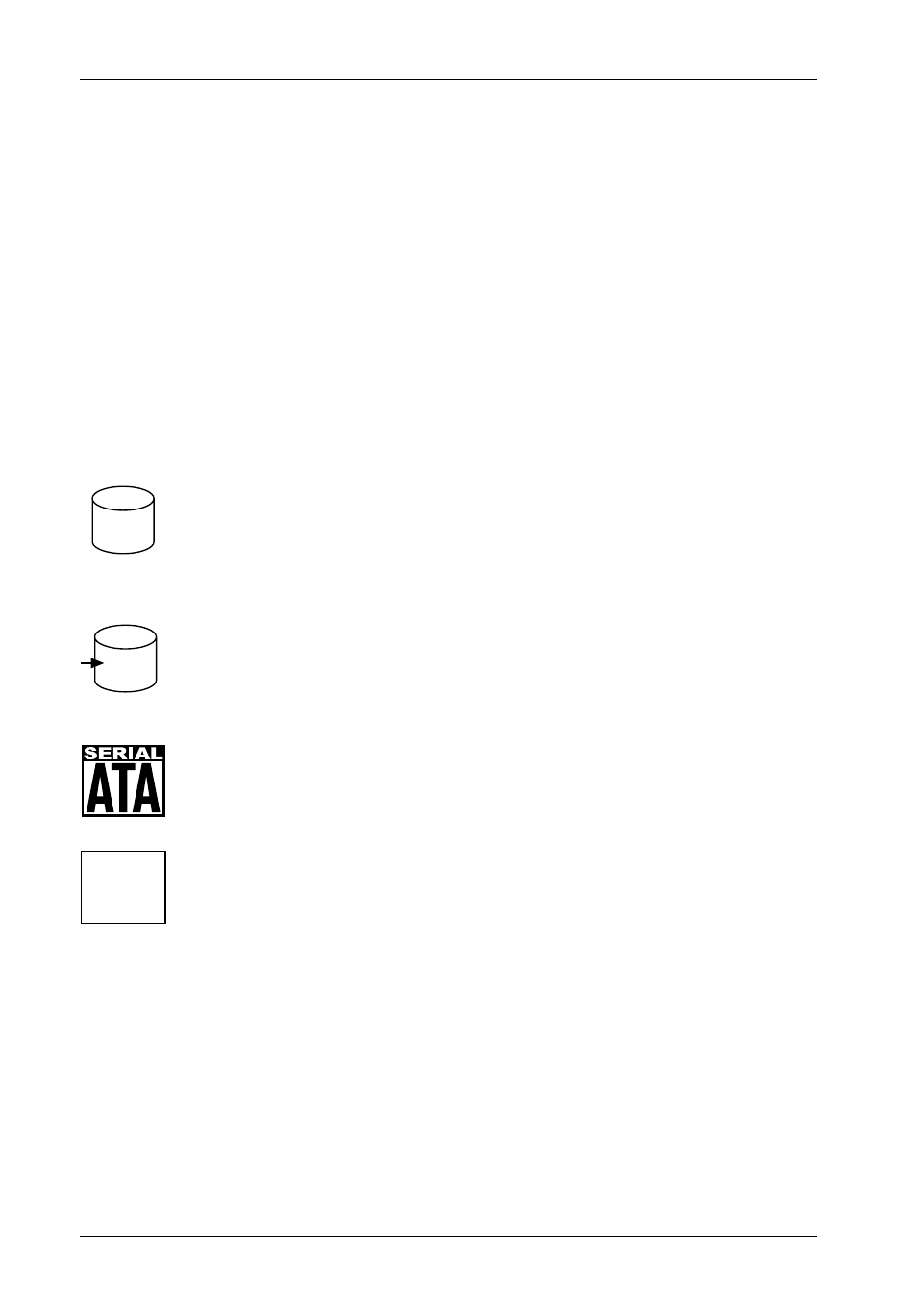
AMBER glow indicates drive is being accessed *
Drive Activity LED
Drive Ready/
Drive Fault LED
BLUE glow indicates that drive is inserted and
ready for access
RED glow indicates drive failure *
Serial ATA logo indicates drive carrier is for
Serial ATA drives
NO logo indicates drive carrier is for
Parallel ATA drives
*
If your PCI-based RAID controller supports these features, cable connections
(cables not included) to the Activity LED and Fault LED pins located on the Option
Pin Connector (Figure 6) are required. Refer to the PCI-based RAID controller manu-
facturer's documentation for further information.