StorCase Technology DE200 Ultra320 User Manual
Page 17
StorCase Technology, Inc.
Ultra320 DE200 User's Guide - Rev. A01
10
Installation
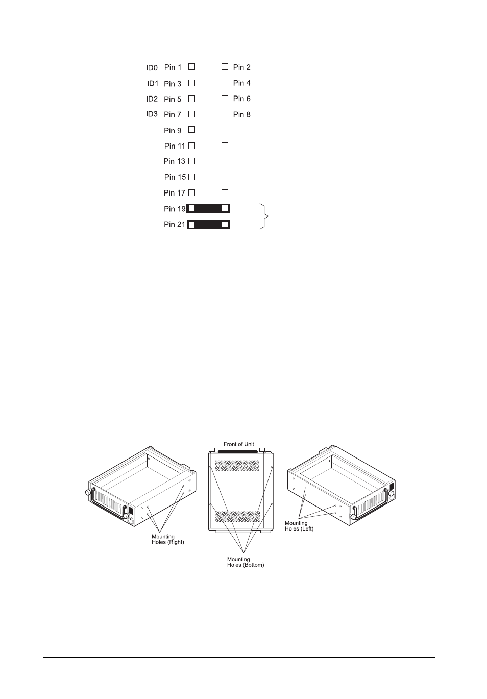
Figure 8: Receiving Frame Mounting Holes
Figure 7: Receiving Frame Motherboard Option Pins (W1)
0496a
4.
With the drive carrier locked in place inside the receiving frame, install the DE200 into
the 5.25” drive opening in the computer or expansion chassis. Use the appropriate
guides to position the DE200 , and fasten it into place with the four (4) #6-32 Phillips
screws provided. Figure 8 illustrates the location of the mounting holes. Mounting holes
are provided on each side and the bottom of the receiving frame to accommodate a
variety of mounting configurations. Use the mounting holes which best suit the com-
puter or expansion chassis configuration.
Pin 10
Pin 12
Pin 14
Pin 22
Pin 20
Pin 18
Pin 16
0439h
SYNC
RMST
DYST
Factory-Installed Jumpers
(Do Not Remove!)
RESERVED
RESERVED
RESERVED
RESERVED
- DE100i-SW (35 pages)
- DE50 (27 pages)
- DE110 (33 pages)
- DE110 (2 pages)
- DE110 (31 pages)
- DE110 (27 pages)
- DE50 (33 pages)
- DX115 (25 pages)
- DE75i-A (31 pages)
- DE75i-A66 (29 pages)
- DE75i-A100 (31 pages)
- SATA DE75 (28 pages)
- DE75i-S (31 pages)
- DE75i-SW (33 pages)
- DE75i-SWC (33 pages)
- DE75i-SW160 (29 pages)
- S20A114 (29 pages)
- DE75i-SWC160 (29 pages)
- DE90i-A (29 pages)
- DE90i-A66 (23 pages)
- DE90i-A100 (23 pages)
- DE90i-S (25 pages)
- DE100i-A (33 pages)
- DE100i-A66 (29 pages)
- DE100i-A100 (29 pages)
- DE100i-CSWTN (2 pages)
- DE100i-S (39 pages)
- DE100i-SWD (33 pages)
- DE100i-SWU2 (37 pages)
- DE100i-SWCU2 (33 pages)
- DE100i-SWU2X (35 pages)
- DE100i-SW160 (35 pages)
- S20A102 (33 pages)
- DE100i-SWC160 (39 pages)
- Ultra320 DE100 (31 pages)
- DE110 (27 pages)
- DE110 (31 pages)
- DE110 (29 pages)
- DE150i-SWC (33 pages)
- DE200i-S (33 pages)
- DE200i-CSWTN (2 pages)
- DE200i-SW (35 pages)
- DE200i-SWU2 (37 pages)
- DE200i-SWCU2 (35 pages)
- S20A108 (33 pages)