Installing the receiving frame – StorCase Technology DE200 Ultra320 User Manual
Page 16
Ultra320 DE200 User's Guide - Rev. A01
StorCase Technology, Inc.
Installation
9
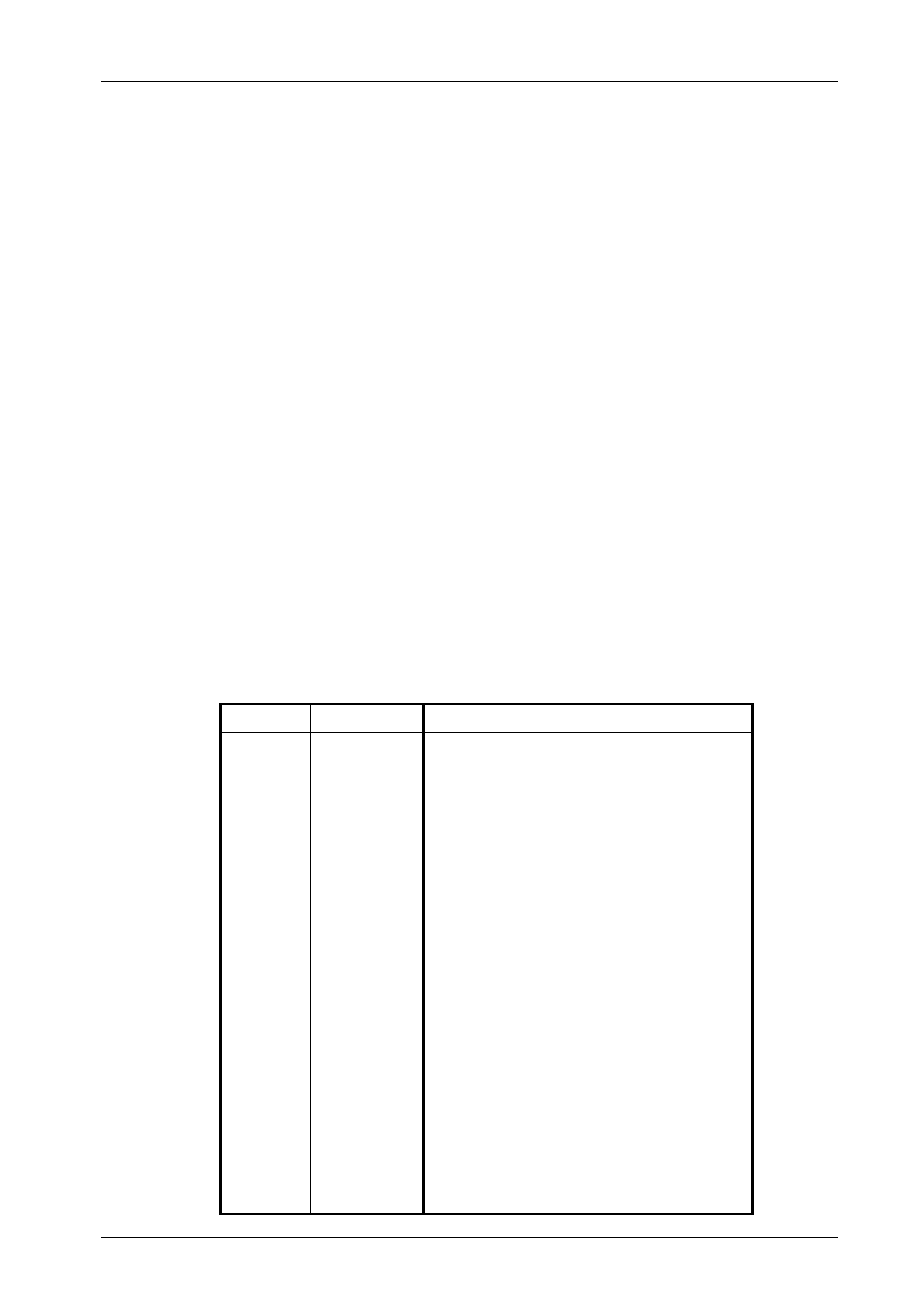
Table 1: Option Pin Connector (W1) Signal Descriptions
1
ID0
SCSI ID
2
GND
Ground
3
ID1
SCSI ID
4
GND
Ground
5
ID2
SCSI ID
6
GND
Ground
7
ID3
SCSI ID
8
GND
Ground
9
Reserved
10
Reserved
11
SYNC
Drive Synchronous Signal
12
GND
Ground
13
RMST
Remote Start (see Table 2)
14
GND
Ground
15
DYST
Delay Start (see Table 2)
16
GND
Ground
17
Reserved
18
Reserved
19
Reserved
20
Reserved
21
Reserved
22
Reserved
PIN
Signal
Function
Installing the Receiving Frame
NOTES:
For SCSI Ultra320 operation, the Ultra320 DE200 requires Ultra320 drives,
Ultra320 HBA, and Ultra320-compliant cabling (internal and external).
Use a #2 Phillips screwdriver during this procedure.
The drive should be installed into the carrier before installing the receiving frame into the
mounting bay of a computer or expansion chassis.
1.
Turn OFF power to the computer.
2.
Open the computer system according to the manufacturer’s instructions. If necessary,
temporarily remove any expansion boards that may make installation difficult.
3.
To select the DE200 unit ID remotely through the computer system or external expansion
chassis, the appropriate cable from the system must be connected to the Option Pin
Connector (W1) on the rear of the receiving frame as shown in Table 1 and Figure 7.