Receiving frame rear panel – StorCase Technology DE200 Ultra320 User Manual
Page 12
Introduction
5
Ultra320 DE200 User's Guide - Rev. A01
StorCase Technology, Inc.
Receiving Frame Rear Panel
(Figure 5)
• I/O Connector (J2) : The input/output connector provides a standard interface for
16-bit wide SCSI signals.
• DC Power Connector (P1): The Data Express uses a standard 4-pin DC power connec-
tor to accept DC power.
• Option Pin Connector (W1):
Remote Unit ID Selection: Pins 1-8 of this connector are provided for remote unit
SCSI ID selection through the computer system. Remote ID selection requires that the unit
ID switch located on the inside of the receiving frame be set to "0". (Onboard ID selection
is set with a switch located on the inside of the receiving frame as shown in Figure 9).
See Table 1 for pin assignments.
Factory-Installed Jumpers: There are three (3) jumpers factory-installed on W1.
These jumpers are located on Pins 9 & 10, 19 & 20, and Pins 21 & 22.
NOTE:
Do not remove these jumpers!
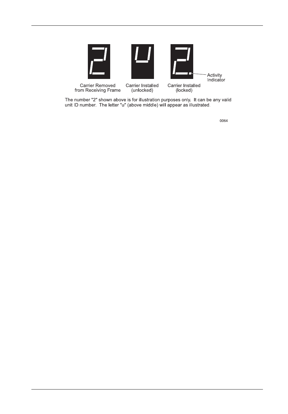
Figure 4: Receiving Frame Unit ID Number and Activity Display