Receiving frame front panel – StorCase Technology DE100i-SW160 User Manual
Page 11
4
Introduction
StorCase Technology, Inc.
DE100i-SW160 User's Guide - Rev. C01
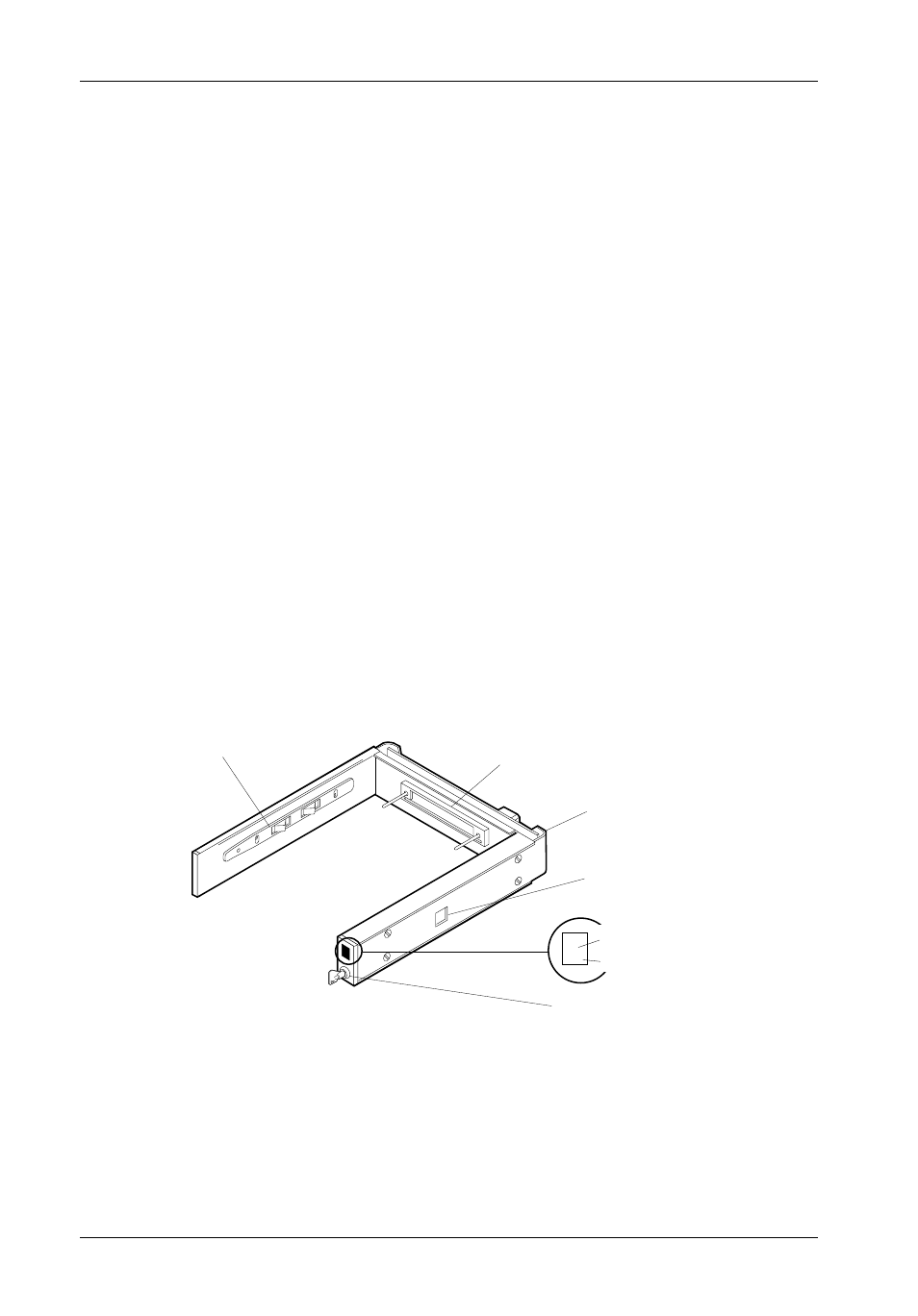
Receiving Frame Front Panel
(Figure 3)
Key Lock/Drive Power Switch - This key switch assures proper seating of the
drive carrier within the receiving frame, turns power to the drive carrier on and off,
and prevents unauthorized removal or installation of the carrier. For the computer
to access data on the disk drive, the key must be turned counterclockwise to the
locked position.
The key can be permanently attached to the locking mechanism as shown in
Appendix C.
Unit ID Number Indicator - (Figure 4) This LED displays the physical address of
the DE100i-SW160 drive carrier if the carrier is Installed and Locked in the receiving
frame or if the carrier is Removed from the receiving frame. If the carrier is Installed
but Not Locked in the receiving frame, a "u" will be displayed to indicate an unlocked
condition. The unit ID number is selected by means of the unit ID select switch inside
the receiving frame using a special alignment tool supplied with the DE100i-SW160.
Activity Indicator- A small dot next to the Unit ID Number which illuminates to show
when the host computer is accessing the data on the DE100i-SW160 carrier. This
dot will flash during communication with the host computer.
Figure 3: Receiving Frame Front Panel
Receiving Frame
Front
Key Lock/Drive
Power Switch
2.
Unit ID Number
Indicator
Activity Indicator
0231A
Device Spin
Down/Up
Timer Switch
Carrier Guide
High Insertion
Count Mating
Connector
All Steel
Receiving
Frame