StorCase Technology DE90i-A66 User Manual
Page 16
DE90i-A66 User's Guide - Rev. A01
StorCase Technology, Inc.
Installation
9
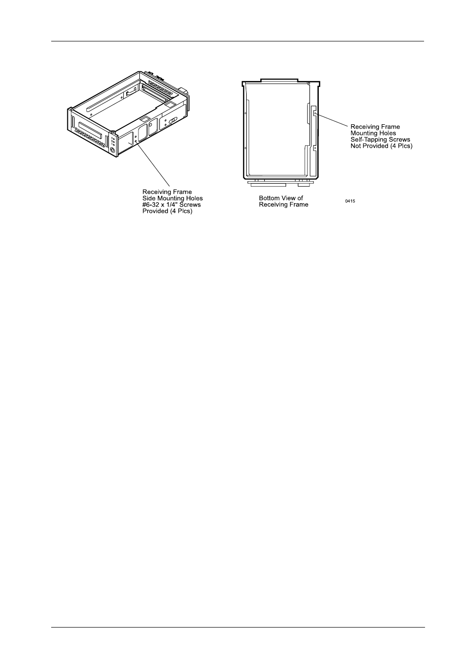
Figure 7: Receiving Frame Mounting Holes
6.
Connect the I/O cable from the host adapter to the receiving frame. The Pin 1
indicator on the cable must be properly aligned. Refer to Figure 3 for the
correct Pin 1 location.
7.
Connect the power cable from the DC power supply in the computer or
expansion chassis to the power connector on the DE90i-A66 receiving frame.
Refer to Figure 3 for the receiving frame power connector location.
8.
Replace any expansion boards that may have been removed earlier. Replace
the system cover according to the manufacturer's instructions.
9.
Reconnect any system or peripheral cables removed earlier.
10.
Turn on power to the computer. If the installation has been successful, and all
the cables have been properly attached, the system should boot normally.
Although the computer may not recognize the DE90i-A66 yet, the appropriate
front panel LED indicators on the DE90i-A66 receiving frame should illuminate.
NOTE: The lock on the DE90i-A66 receiving frame functions as a lock and a
DC power switch for the carrier unit. The lock must be engaged
(turned counterclockwise) in order to supply power to the carrier and
installed drive.
11.
The new drive may need to be formatted or initialized prior to use with the
operating system and applications software. Refer to the drive and/or
computer manufacturer's documentation for formatting information.