Receiving frame rear panel – StorCase Technology DE90i-A66 User Manual
Page 12
DE90i-A66 User's Guide - Rev. A01
StorCase Technology, Inc.
Introduction
5
Receiving Frame Rear Panel
(Refer to Figure 3)
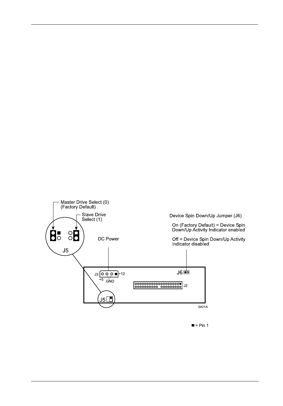
DC Power Connector (J3): The DE90i-A66 uses a standard 4-pin DC Power
Connector to accept DC power.
I/O Connector (J2): The input/output connector provides a standard interface
for all IDE signals. See Table 3 for J2 pin assignments.
Master/Slave Selection Jumper (J5): Master Drive configuration (default).
Forces Master Drive configuration on receiving frame. Change jumper to set
Slave Drive configuration. Refer to Figure 6 for further information.
NOTE:
If both jumpers are installed or if both jumpers are removed, all front
panel indicator LEDs will flash indicating an error (Refer to Table 2).
Device Spin Down/Up Timer Jumper (J6): Jumper installed (factory default)
enables device spin down/up visual indicator. Receiving frame front panel
indicator LED (Figure 2) will flash to indicate device spin down/up.
Figure 3: Receiving Frame (Rear View)