StorCase Technology DE90i-A User Manual
Page 18
DE90i-A User's Guide - Rev. B02
StorCase Technology, Inc.
Installation
11
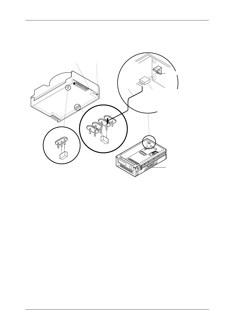
Figure 6: Typical AT/IDE Drive Connections
Typical AT/IDE drive jumper positions are shown in Figure 6. Remove and save all the jumpers.
Install a wire (not provided) from the -C/D pin to the connector provided with the DE90i-A:
-C/D The darkened pin in the figure above is connected to Pin 1 of the provided wire
wrap connector.
-DSP Install the jumper in the DSP position as shown in Figure 6.
Install the wire wrap connector onto J3 on the carrier circuit board.
J4, Pin 1
Power
Connector
J2, Pin 1
AT/IDE
Interface
J3 Pin1
E1
E2
E3
C/D
SS
DSP
J3 Pin 1
Required
Jumper
Wire
Drive
Carrier
3-PIN WIRE WRAP CONNECTOR
(Provided). Used for fabricating a single
wire connection (wire not provided)
between the drive and J3 Pin 1 on the
drive
carrier circuit board.
Data
Expre
ss
0422
Sto
rCa
se
- DE100i-SW (35 pages)
- DE50 (33 pages)
- DE50 (27 pages)
- DE110 (33 pages)
- DE110 (2 pages)
- DE110 (31 pages)
- DE110 (27 pages)
- DX115 (25 pages)
- DE75i-A (31 pages)
- DE75i-A66 (29 pages)
- DE75i-A100 (31 pages)
- SATA DE75 (28 pages)
- DE75i-S (31 pages)
- DE75i-SW (33 pages)
- DE75i-SWC (33 pages)
- DE75i-SW160 (29 pages)
- S20A114 (29 pages)
- DE75i-SWC160 (29 pages)
- DE90i-A66 (23 pages)
- DE90i-A100 (23 pages)
- DE90i-S (25 pages)
- DE100i-A (33 pages)
- DE100i-A66 (29 pages)
- DE100i-A100 (29 pages)
- DE100i-CSWTN (2 pages)
- DE100i-S (39 pages)
- DE100i-SWD (33 pages)
- DE100i-SWU2 (37 pages)
- DE100i-SWCU2 (33 pages)
- DE100i-SWU2X (35 pages)
- DE100i-SW160 (35 pages)
- S20A102 (33 pages)
- DE100i-SWC160 (39 pages)
- Ultra320 DE100 (31 pages)
- DE110 (29 pages)
- DE110 (27 pages)
- DE110 (31 pages)
- DE150i-SWC (33 pages)
- DE200i-S (33 pages)
- DE200i-CSWTN (2 pages)
- DE200i-SW (35 pages)
- DE200i-SWU2 (37 pages)
- DE200i-SWCU2 (35 pages)
- S20A108 (33 pages)