Electrical connections, Pwr connector ctrl connector, Optimax-rp244 – Star Headlight & Lantern RSK244-2 Strobe Kit User Manual
Page 5: Optimax-rp242, All heads on and off together, Separate front and rear activation, All heads on and off together (high power only), All heads on and off together (low power only)
-3-
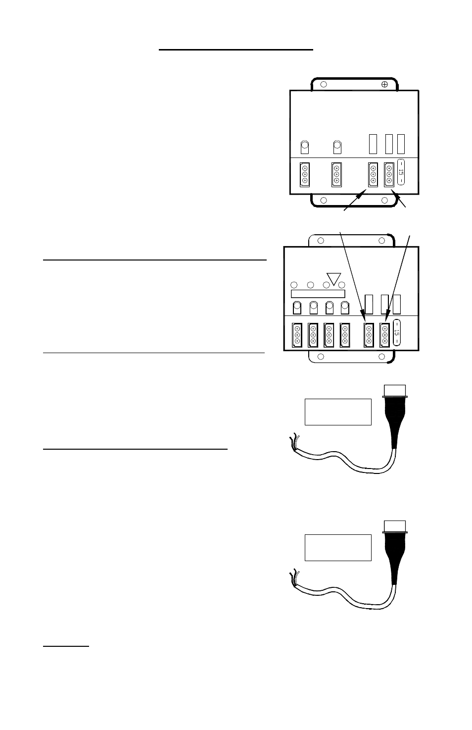
Electrical Connections
There are a number of different configurations you may choose from when installing the
RP242 and RP244 strobe packs:
•
All Heads On and Off Together
(High Power Only)
•
All Heads On and Off Together
(Low Power Only)
•
All Heads On and Off Together
(High/Low switching Option)
•
Separate Front and Rear Activation
(High Power Only)
†
•
Separate Front and Rear Activation
(Low Power Only) †
•
Separate Front and Rear Activation
(High/Low Switching Option)
†
† - RP244 Only
Decide which configuration will work best for you and
proceed to the appropriate section, referring to the
proper wiring diagram on page 5 or 6.
All Heads On and Off Together (High Power Only)
(This setup is typically used for most “On/Off” applications)
1. The black and white wires from your PWR plug wire
should be connected to a good chassis ground.
2. The red wire from your PWR plug and the black and
white wires from the CTRL plug should be
connected to +12VDC through your On/Off switch.
All Heads On and Off Together (Low Power Only)
1. The black wire from your PWR plug on the pack should
be connected to a good chassis ground.
2. The red and white wires from your PWR plug and the
black and white wires from the CTRL plug should be
connected to +12VDC through your On/Off switch.
All Heads On and Off Together
(With High/Low Power Switching Option)
1. The black wire from your PWR plug on the pack should
be connected to a good chassis ground.
2. The red and white wires from your PWR plug and the
black and white wires from the CTRL plug should be
connected to +12VDC through the On/Off switch of
the SP3860-2H-OP (not included).
3. The white wire from the PWR plug allows utilization
of the High/Low (Day/Night Mode) option. The white
wire from your PWR plug should be connected to the
High/Low switch on the SP3860-2H-OP (not included).
When the white wire is connected to power through
your second switch the pack will operate under low
power (Night Mode). When the second switch is in
the “off” position, your pack will run under high power
(Day Mode).
CAUTION: If you are using your own switch panel with the High/Low option, only apply
power (+12VDC) to the white wire when the pack is on. Applying constant voltage to the
white wire on the PWR connector while the pack is switched off may result in damage to
the circuitry of the pack and will void the warranty. The SP3860-2H-OP (not included) is
designed to comply with this requirement.
OPTIMAX-RP244
HV
T4
T3
T2
T1
15AMP
CTRL
PWR
L4
L3
L2
L1
(Connect to +12VDC for Low Power)
POWER PLUG FOR
RP242 and RP244
PWR
CONNECTOR
OPTIMAX-RP242
L1
15AMP
L2
PWR
CTRL
Red = Power
Black or Blue = Ground
White = HI/LO Option
Red = Pattern Select
Black = On/Off Heads 1 & 3
(RP244 Only)
White = On/Off Heads 2 & 4
(RP244 Only)
CTRL PLUG FOR
RP242 and RP244
CTRL
CONNECTOR
PWR
Connector
CTRL
Connector