Strobe packs manufactured prior to june 2005, Rev. a strobe packs manufactured since june 2005, Wiring diagram for ne w st yle – Star Headlight & Lantern RSK244-2 Strobe Kit User Manual
Page 16: Wir ing dia gra m f or ol d styl e
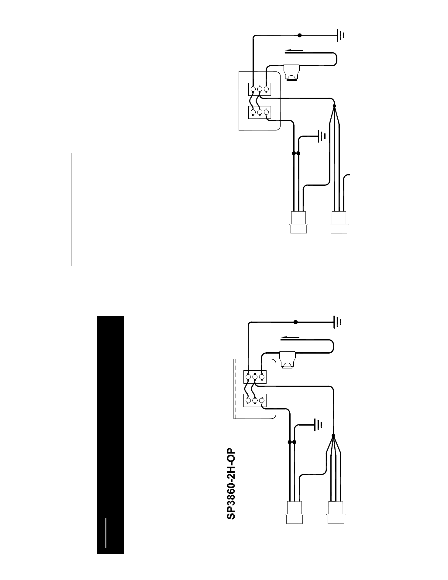
Connecting SP3860-2H-OP to:
Old Style RP242, RP244, and RP906 Packs
(Strobe packs manufactured prior to June 2005
DATE
CODE
2
2
0
5
)
1. Connect
th
e
black
w
ire from y
our pow
er plug on the strobe pack and the
black
w
ire from the
sw
itch panel to a good chassis ground.
2. Connect
th
e
red
w
ire from y
our pow
er plug and all three w
ires from the CTRL connector to
the
red
w
ire ex
tending from terminal 2 of SW1.
This w
ill place y
our pack into five-flash
mode. Please review
the strobe pack ow
ner
’s manual for alternate flash patterns.
3. The
wh
it
e w
ire from the pow
er plug allow
s utilization of the HI/LO
(Day
/Night Mode)
option. Connect th
e
wh
it
e w
ire from y
our PWR plug t
o
th
e w
h
ite
w
ire from terminal 1 of the
H
ig
h/
Lo
w
s
w
itc
h
(S
W
2)
. When the
wh
it
e w
ire is connected to pow
er through SW2 the
pack w
ill operate in “Night Mode” (low
pow
er).
When SW2 is in the “off” position, y
our
pack w
ill run in high pow
er mode.
4. The
fused
lead
from terminal 1 of SW1 on the sw
itch panel w
ill connect to y
our +12VDC
pow
er supply
.
5.
When properly
w
ired, SW1 w
ill be on the left side (Front View
) and sw
itch the pack on
and off. SW2 w
ill be located on the right side of the sw
itch panel and w
ill be used to
select betw
een low
or high pow
er.
If you have any questions concerning this or any other Star product,
please contact our Customer Servi
ce Department at (585) 226-9787.
Connecting SP3860-2H-OP to:
New Style RP242 and RP244 Packs
(REV. A
strobe packs manufactured since June 2005
D
A
T
E C
O
D
E
2205
)
A
ll Heads On and Off Together
(W
ith High/Low Power Switching Option)
1. Connect
th
e
black
w
ire from y
our pow
er plug on the strobe pack and the
black
w
ire from
the sw
itch panel to a good chassis ground.
2. Connect
th
e
red
w
ire from y
our PWR plug and the
black
and
wh
it
e w
ires from the
CTRL plug t
o
th
e
red
w
ire
fr
om
terminal 2 of the On/Off sw
itch (SW1).
3. The
wh
it
e w
ire from the PWR plug allow
s utilization of the HI/LO
(Day
/Night Mode)
option. Connect th
e
wh
it
e w
ire from y
our PWR plug t
o
th
e w
h
ite
w
ire from terminal 1 of
the High/Low
sw
itch (SW2).
W
he
n
th
e
wh
it
e w
ire is connected to pow
er through SW2
the pack w
ill operate in “Night Mode” (low
pow
er). When SW2 is in the “off” position,
your pack w
ill run in high pow
er mode.
The
red
w
ire from the CTRL connector allow
s y
ou to select the flash pattern y
ou w
ish to
have y
our strobe pack display
. The pack is def
aulted for Five-Flash mode. Y
ou can scroll
through Pseudo-Random, Singleflash, Doubleflash
, Tripleflash, Quadflash, and back to
Five-Flash by
turning y
our strobe lights on and briefly
touching the
red
CTRL w
ire to
+12VDC and releasing it. Continue to briefly
touch and release this w
ire to +12VDC until
you find the pattern desired. Once y
ou have the pattern y
ou like, tape the end of the
red
w
ire from the CTRL connector so that it
does not come into contact w
ith +12VDC.
If you have any questions concerning this or any other Star product,
please contact our Customer Servi
ce Department at (585) 226-9787.
WARNING:
DO
NO
T USE THE FIVE FLA
SH PA
TTERN IF YO
U O
N
LY A
R
E
CONNECTING TWO HEA
D
S TO THE RP244 OR RP906. DISCONNECTING THE
RED CTRL WIRE WILL PLA
C
E THE PA
CK INTO QUA
D
FLA
SH MODE.
SP3860-2H-OP
Wiring Diagram for
Ne
w
St
yle
RP24
2/RP244
O
n/O
ff w/
Hi
gh-L
ow P
ower
Sw
itchi
ng
(* All
heads activate
to
gether)
WH
ITE
P
LU
G
S
IN
T
O
P
O
W
E
R
P
A
K
CT
RL
CON
N
ECTOR
RED
BLA
C
K
P
LU
G
S
IN
T
O
P
O
W
E
R
P
A
K
POWE
R
CON
N
ECTOR
WH
ITE
RED
BLA
C
K
P
att
ern
S
ele
ct:
To
uc
h a
n
d
re
le
as
e t
o
+
1
2V
D
C
to
set
pa
tte
rn
th
en
tap
e o
ff
1
1
SW1
OFF
HIGH
SW2
RED
LIG
H
T
E
D SWI
T
CH PAN
EL
(REAR
VIEW)
ON
LOW
2
3
2
3
WHI
T
E
15 AM
P
FUSE
G
OOD
CH
AS
SI
S
GR
OUN
D
CONNEC
T TO +1
2 VDC
BLACK
Wir
ing
Dia
gra
m f
or
Ol
d Styl
e
RP242/RP244/RP90
6
On/Of
f w/
High-Low
Power
Switching
(* All he
ads activa
te
tog
et
he
r)
WHITE
P
L
U
G
S
IN
T
O
P
O
W
E
R
P
A
K
CT
RL
CO
NNEC
T
O
R
RE
D
BL
AC
K
P
L
U
G
S
IN
T
O
P
O
W
E
R
P
A
K
POWER
CO
NNEC
T
O
R
WHITE
RE
D
BL
AC
K
1
1
SW
1
OFF
HI
G
H
SW2
RED
LIGH
T
ED SWITCH
PANEL (REA
R VIEW)
ON
LOW
2
3
2
3
WHIT
E
15 A
MP
FUSE
GOO
D
C
H
A
SSI
S
GR
OU
ND
CONN
ECT
TO +
12 V
DC
BLAC
K