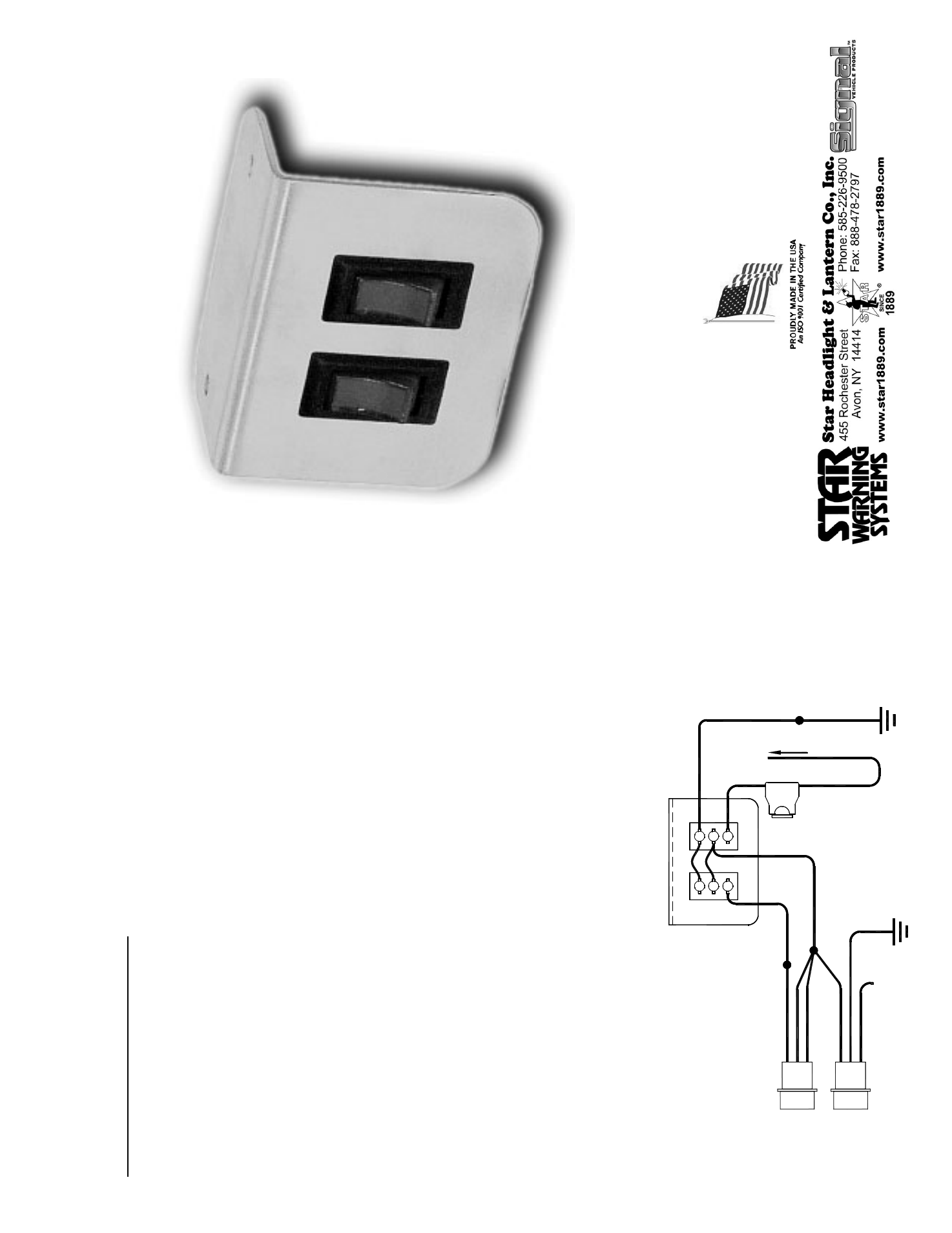
On/off)(hi/lo) switch panel, Wiring diagram for new s tyle – Star Headlight & Lantern RSK244-2 Strobe Kit User Manual
Page 15
PLITSTR283 REV. B 8/08/05
Connecting SP3860-2H-OP to:
RP966 and RP996 Packs
A
ll Heads On and Off Together
(W
ith High/Low Power Switching Option)
1.
Be sure that the
High-Low
/3-Pair Head Select Jumper
is in the High-Low
position,
tow
ards the right
(see RP966/RP996 Owners M
anual)
.
2. Connect
th
e
black
w
ire from y
our pow
er plug on the strobe pack and the
black
w
ire from
terminal 3 of SW1 on the sw
itch panel to a good chassis ground.
3.
Connect
the
black
and
red
w
ires from the ENABLE plug and the
red
w
ire from the
POWER plug t
o
th
e
red
w
ire from SW1 (the On/Off sw
itch).
4. The
wh
it
e w
ire from the ENABLE plug allow
s utilization of the HI/LO
(Day
/Night Mode)
option. T
he
wh
it
e wi
re
fr
om
yo
ur
E
N
A
B
LE
p
lu
g should
be
connected
to
the
wh
it
e wi
re
fr
om
te
rm
in
al
1
o
f S
W
2.
When
the
wh
it
e w
ire is connected to pow
er through y
our
second sw
itch the pack w
ill run in high pow
er mode. When SW2 is in the “off” or
“LO
W
” position, y
our pack w
ill operate in “Night Mode” (low
pow
er).
The
wh
it
e w
ire from the POWER connector allow
s y
ou to select the flash pattern y
ou w
ish
to have y
our strobe pack display
. Y
ou can scr
oll through 24 different patters (listed below
)
by
turning y
our strobe lights on and briefly
touching the
wh
it
e POWER w
ire to +12VDC and
releasing it. Continue to br
iefly
touch and release this w
ire to +12VDC until y
ou find the
pattern desired. Once y
ou have the pattern y
ou like, tape the end of the
wh
it
e w
ire from the
POWER connector so that it does not come into contact w
ith +12VDC.
If you have any questions concerning this or any other Star product,
please contact our Customer Servi
ce Department at (585) 226-9787.
SP3860-2H-OP
(ON/OFF)(HI/LO) Switch Panel
The SP3860-2H-OP can be used w
ith a number of different strobe packs. To properly
connect the sw
itch panel, please locate the appropriate section for y
our application
and follow
those instructions.
RED
P
L
U
G
S
IN
T
O
P
O
W
E
R
P
A
K
ENABL
E
CON
N
E
CT
OR
WH
IT
E
BL
ACK
P
L
U
G
S
IN
T
O
P
O
W
E
R
P
A
K
POWER
CON
N
E
CT
OR
WH
IT
E
RED
BL
ACK
Pat
ter
n Se
lect
:
Touch a
nd r
elea
se
to
+12VD
C
to
set
pat
te
rn
then
tape
of
f
1
1
SW1
OFF
LOW
SW
2
RED
G
OOD
CHA
SSI
S
GR
OUN
D
BLA
CK
LIGHTED
SWI
T
CH
PANEL (REAR VIEW
)
ON
HIG
H
2
3
2
3
GO
OD
CH
ASSI
S
GR
O
U
N
D
15 A
MP
FUSE
CONNECT TO +
12
VDC
SP3860-2H-OP
Wiring Diagram for
New
S
tyle
RP9
66/RP99
6
On/Off w/Hi
gh-Low P
ower S
w
itching
All heads activate toget
her
(Set
Str
obe Pa
ck
Jum
per
in H
ig
h
/L
ow
Op
tion
Posit
io
n
)
WH
IT
E
1. Simultaneous
Singleflash
2.
Alternating Single flash
3. Alternating
Doubleflash
4. Alternating
Tripleflash
5. Alternating
Quadflash
6.
Alternating Quintflash
7. Double-Duty
8. Doubleflash
Alternating,
Doubleflash Simultaneous
9. Alternating
Climber
10. Leadfoot
11.
Singleflash Knight Rider Effect
†
12.
Quadflash Knight Rider Effect
†
13. Doubleflash
Left
†
14. Doubleflash
Right
†
15.
Quadflash Center Out
†
16. Quadflash
W
arning
†
17. Pseudo-Random
18.
Delta Omega Sw
eep
19.
Alternating Quadflash & Alternating Single flash Combo
20.
Delta Omega Sw
eep, Alternating Quintflash &
Alternating Doubleflash Combo
(DE
F
AULT)
21.
Alt. Doubleflash, Simu
ltaneous Doubleflash, Leadfoot,
Pseudo-Random & Alt. Quadflash Combo
22.
Alternating Climber, Double-Duty
, Alternating
Quintflash & Alternating Quadflash Combo
23.
Cy
cle Through Patterns 1 - 10, 17 & 18
24.
Cy
cle Through All Patterns
† -
T
raf
fic D
irector
ty
pe patter
n
s -
w
ith onl
y tw
o heads
enabled, these patterns w
ill all be Quadf
lash W
a
rn.