Wiring, Grounding the module, System wiring guidelines – Spectrum Controls 1762sc-OF8 User Manual
Page 9
MicroLogix™ Analog Output Module
16
Publication 0100163-01 Rev. B
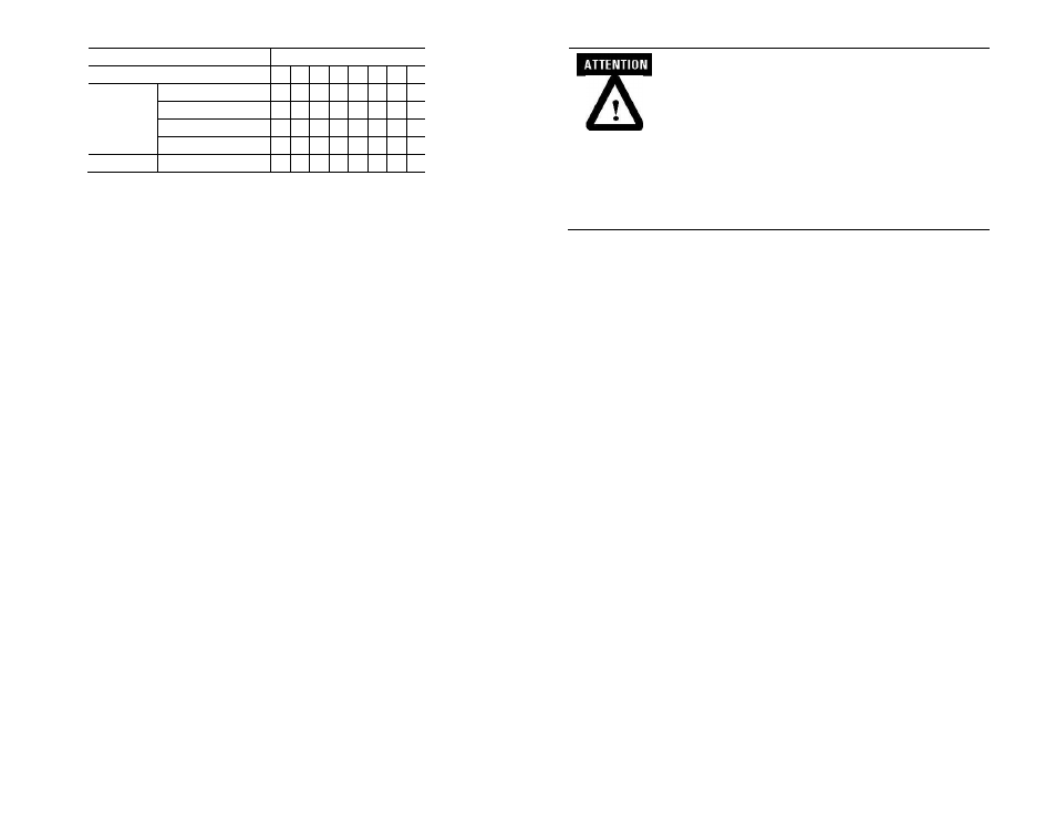
To Select
Make these bit settings
7 6 5 4
3
2
1
0
Data Format
Scaled for PID
0
0
Engineering Units
0
1
Percent Range
1
0
Raw/Proportional Data
1
1
Unused
0 0 0
MicroLogix™ Analog Output Module
9
Publication 0100163-01 Rev. B
EXPLOSION HAZARD
• In Class I, Division 2 applications, the bus connector must
be fully seated and the bus connector cover must be snapped
in place.
• In Class I, Division 2 applications, all modules must be
mounted in direct contact with each other as shown on page
6. If DIN rail mounting is used, an end stop must be
installed ahead of the controller and after the last 1762 I/O
module.
Wiring
Grounding the Module
Grounding for this product is provided by the MicroLogix™ 1100, 1200 or 1400
CPU via the bus ribbon cable. Refer to Industrial Automation Wiring and Grounding
Guidelines, Allen-Bradley publication 1770-4.1, for additional information.
System Wiring Guidelines
Consider the following when wiring your system:
The analog common (COM) is not connected to earth ground inside the
module. All terminals are electrically isolated from the system.
Use Belden™ 8761, or equivalent, shielded wire.
Under normal conditions, the drain wire (shield) should be connected to
the metal mounting panel (earth ground) as close to the module as
possible. Keep the shield connection to earth ground as short as possible.
To ensure optimum accuracy for voltage type outputs, limit overall cable
impedance by keeping all analog cables as short as possible. Locate the
I/O system as close to your voltage type sensors or actuators as possible.
Digital and analog power must be supplied by an Isolated Secondary
Limited Energy Low Voltage source.
Use supply wires for 20˚ C above surrounding ambient.