Terminal block layout, Labeling the terminals – Spectrum Controls 1762sc-OF8 User Manual
Page 10
MicroLogix™ Analog Output Module
10
Publication 0100163-01 Rev. B
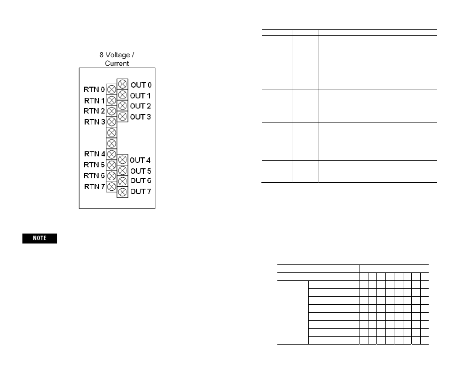
Terminal Block Layout
Grounding the cable shield at the module end only usually
provides sufficient noise immunity. However, for best cable
shield performance, earth ground the shield at both ends, using a
0.01µF capacitor at one end to block AC power ground currents,
if necessary.
Labeling the Terminals
A write-on label is provided with the module. Remove the label from the door,
mark the identification of each terminal with permanent ink, and slide the label
back into the door.
MicroLogix™ Analog Output Module
15
Publication 0100163-01 Rev. B
Commands
Command Value
Description
Unlock 0xFFF0
This MUST be the first command issued after entering
Command Mode. If not, an error will be posted.
Data Words are ignored.
The module does not need to detect a command transition
to Unlock. It simply waits for the Fixed Words to be valid
and Unlock command set. This command is ignored if
issued multiple times (Response Code will be 0).
Once Command Mode is unlocked it remains unlocked
until it has been successfully configured and the Exit
command issued.
Clear
Command
0xFF00
Clears the command buffer to allow a command to be re-
issued. Since the module only knows a command is issued
when the Command word changes, the only way to re-issue
a command is to cause a transition. This command gives
the user a null command to do that. The response is always
0. No other action is taken with this command.
Load Config
0xFFF1
Data Words 1-4 must contain valid channel configuration
data for all channels. See Data Words table below.
Configuration will be validated. An error will be posted for
the first invalid channel configuration found. If the
configuration is invalid, the configuration info in the Data
Words may be modified but to re-issue the Load Config,
the Clear Command must be issued first.
Exit
0xFF80
Delay 600ms then enter run state with configuration. The
delay begins after the response. If configuration is not
valid, the module will remain in Command Mode until a
valid configuration is entered.
3) Data Words 1-4:
If the command requires valid data in the Data Words, they are validated
and a response is placed in the Response Code register (i.e. Word I:e.1).
The following table lists the possible configuration settings for each of the
8 channels. Each Data Word contains two channel configurations. See
Output Data File table for Data Word layout.
Data Words 1-4
To Select
Make these bit settings
7
6
5
4
3
2
1
0
Output Type
4 to 20 mA
0
0
0
0 to 20 mA
0
0
1
-10 to 10 V
0
1
0
0 to 10 V
0
1
1
1 to 5 V
1
0
0
0 to 5 V
1
0
1
Reserved
1
1
0
Channel Disabled
1
1
1