Wire size and terminal screw torque, Addressing, Input data file – Spectrum Controls 1762sc-OF8 User Manual
Page 12: Configuration data file, Output data file
MicroLogix™ Analog Output Module
12
Publication 0100163-01 Rev. B
Wire Size and Terminal Screw Torque
Each terminal accepts up to two wires with the following restrictions:
Wire Type
Wire Size
Terminal Screw
Torque
Solid
Cu-90°C (194°F)
#14 to #22 AWG
0.904 Nm (8 in-lbs)
Stranded Cu-90°C (194°F)
#16 to #22 AWG
0.904 Nm (8 in-lbs)
I/O Memory Mapping
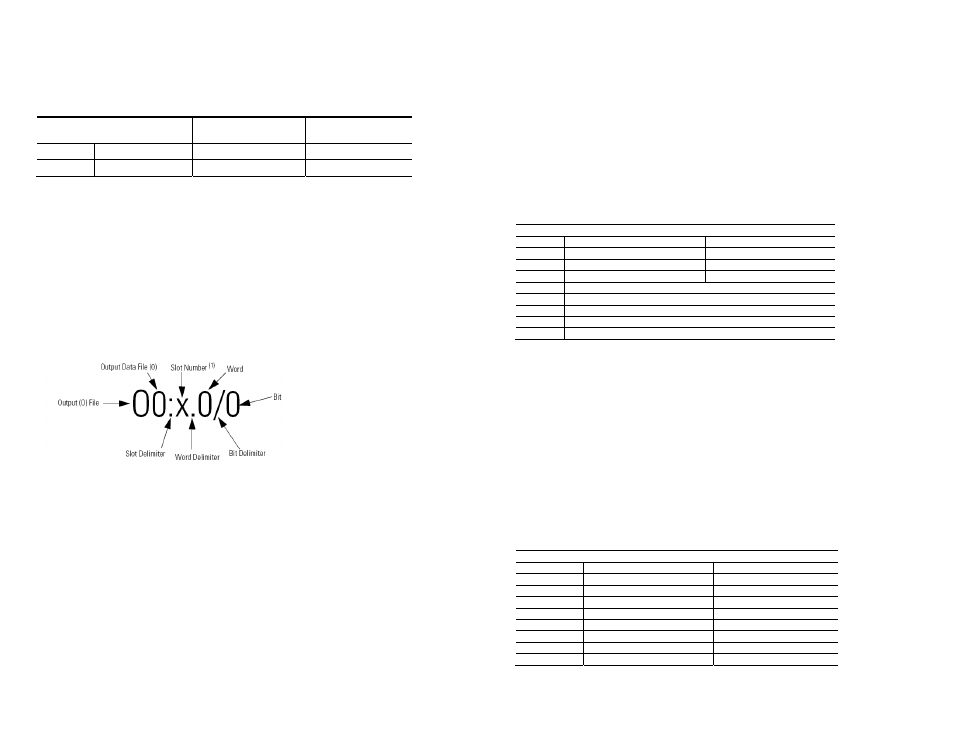
Addressing
The addressing scheme for 1762 Expansion I/O is shown below.
(1)
I/O located on the controller (embedded I/O) is slot 0. I/O added to the controller (expansion I/O) begins
with slot 1.
MicroLogix™ Analog Output Module
13
Publication 0100163-01 Rev. B
Input Data File
For each module, slot x, input words 0 through 7 contain module status
information including channel status and configuration status. During module
configuration, the module enters a special mode called Command Mode. During
Command Mode, configuration data is written to the module using the output data
file and Command Mode response data is returned to words 0 through 2 in the
input data file. After the Command Mode process completes, the module returns
to normal run mode. The table below shows the layout for each word during both
modes of operation.
Input Data File
Input File(Read Only)
Normal Run Mode
Command Mode
I:e.0
General Status Word 0
Command Echo
I:e.1
Output Status Word 1 (ch 0-3)
Response Code
I:e.2
Output Status Word 2 (ch 4-7)
Response Channel
I:e.3
Echo Config (ch 0-1)
I:e.4
Echo Config (ch 2-3)
I:e.5
Echo Config (ch 4-5)
I:e.6
Echo Config (ch 6-7)
I:e.7 Not
Used
Configuration Data File
The configuration data file is not used. Instead the output data file is used to
configure the module and control output channels 0 through 7.
Output Data File
This section describes how the input and output files are used together to configure
the module. The module enters a special mode called Command Mode when the
PLC transitions from Program mode to Run mode. After the module enters
Command Mode, the output file is used to send commands to the module and the
module responds via the input data file. The table below shows the layout for each
word during both modes of operation.
Output Data File
Output File
Normal Run Mode
Command Mode
O:e.0
Channel 0 Data Word
Command
O:e.1
Channel 1 Data Word
Data Word 1 (Ch0 & 1)
O:e.2
Channel 2 Data Word
Data Word 2 (Ch2 & 3)
O:e.3
Channel 3 Data Word
Data Word 3 (Ch4 & 5)
O:e.4
Channel 4 Data Word
Data Word 4 (Ch6 & 7)
O:e.5
Channel 5 Data Word
Fixed Word 1 (0xCDEF)
O:e.6
Channel 6 Data Word
Fixed Word 2 (0xFEDC)
O:e.7
Channel 7 Data Word
Fixed Word 3 (0x5A5A)