Power requirements, Output specifications, Panel mounting – Spectrum Controls 1762sc-OF8 User Manual
Page 7
MicroLogix™ Analog Output Module
18
Publication 0100163-01 Rev. B
Specification Description
Fast Transient Burst
(IEC61000-4-4)
4 kV
Surge Immunity
(IEC61000-4-5)
2 kV Line - Line, 4 kV Line - Gnd
Conducted Immunity
(IEC61000-4-6)
10V, 0.15 to 80 MHz
Output Specifications
Specification Description
Accuracy - Voltage Outputs
System accuracy at 25° C: ± 20 mV maximum
System accuracy at -20-60°C: ± 50 mV maximum
Accuracy - Current Outputs
System accuracy at 25° C: ± 50 uA maximum
System accuracy at -20-60°C: ± 75 uA maximum
Output Resolution (at 25C)
In RAW mode
Voltage Output
370µV per bit average when using RAW format in ±10V range
and 0-10V range
185µV per bit average when using RAW format in 0-5 or 1-5V
ranges
Current Output
380nA per bit when using RAW format for all current ranges
Differential Nonlinearity
±1 LSB
Output Ripple
<15mV ripple for voltage or current
Output Impedance
Current: >1Megohm, Voltage: <1 ohm (MRD)
Output Load
Current: 0 ohm min, 500 ohm max,
Voltage: >=1k ohm at 10V output (10 mA), includes wire
resistance.
Maximum Output Inductive and
Capacitive Load
0.1mH
1µF
Output Settling Time
<1ms to 63% of full scale
Output Channel glitch.
Current mode = < ± 1V for 20ms at maximum load
Voltage mode = < ± 0.4V for 20ms and < ±- 1V for 1.5ms
with 1k ohm load
Output Protection
±24V @25dec C for 1 minute on any channel, with any range
and value
Short Circuit Protection
Yes, continuous. (IEC 1131-2 requirement) with any range and
value
MicroLogix™ Analog Output Module
7
Publication 0100163-01 Rev. B
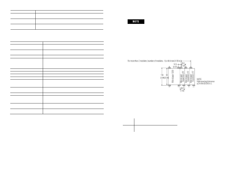
For environments with extreme vibration and shock
concerns, use the panel mounting method described
below, instead of DIN rail mounting.
Panel Mounting
Use the dimensional template shown below to mount the module. The preferred
mounting method is to use two M4 or #8 panhead screws per module. M3.5 or #6
panhead screws may also be used, but a washer may be needed to ensure a good
mechanical contact. Mounting screws are required on every module.
Power Requirements
The maximum number of OF8 modules that can be installed in a system depends
on the maximum bus current draw of the module and the maximum bus current
provided by the PLC. The OF8 module has the following power requirements.
5 VDC
24 VDC
30 mA 250 mA @ 18.7 V, 195 mA @ 24 V
Use the table below to determine the maximum number of OF8 modules that can
be installed in a MicroLogix system.