Spectrum Controls 1762sc-IF4OF4 User Manual
Page 26
3-4
MicroLogix™ 1200 Analog Combo Module (4Ch IN / 4Ch Out)
User’s Manual Pub. 0300247-01 Rev. C
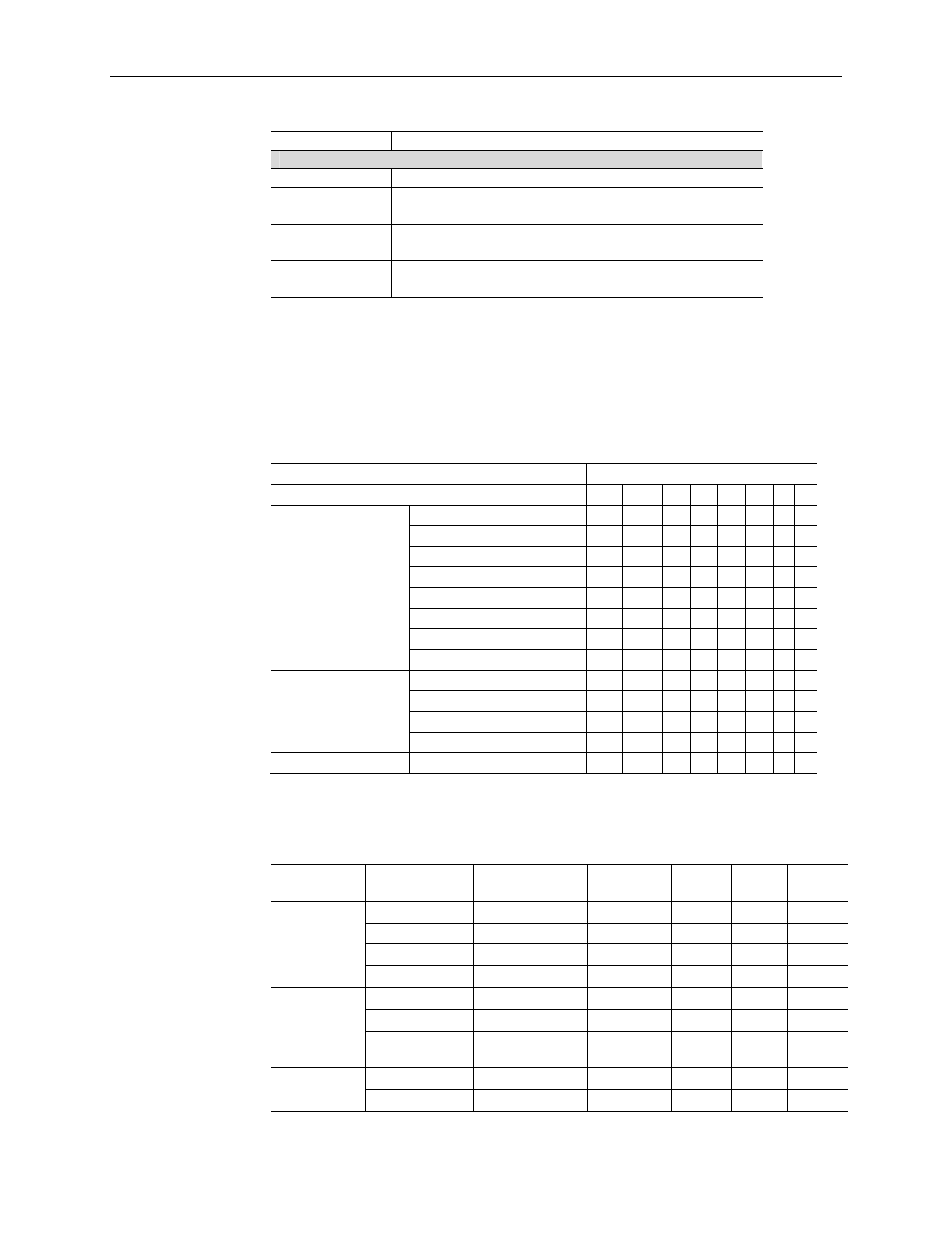
Register Function
Output File (Used for Module Configuration)
High byte: Channel 1 Configuration Register (Output)
1
O:e.5
Low byte: Channel 2 Configuration Register (Output)
1
High byte: Channel 3 Configuration Register (Output)
1
O:e.6
Low byte: Channel 4 Configuration Register (Input)
2
High byte: Channel 5 Configuration Register (Input)
2
O:e.7
Low byte: Channel 6 Configuration Register (Input)
3
High byte: Channel 7 Configuration Register (Input)
3
1
See Table 3-2,
2
See Table 3-4,
3
See Table 3-5
3.4.2 Output Channel Configuration (Channels 0 through 3)
The table below describes the configuration options for analog output channels 0 through
3.
Table 3-2 (Configuration for Output Channels 0 through 3)
To Select
Make these bit settings
7 6 5 4 3 2 1 0
Output Type
4 to 20 mA
0 0 0
0 to 20 mA
0 0 1
-10 to 10 V
0 1 0
0 to 10 V
0 1 1
1 to 5 V
1 0 0
0 to 5 V
1 0 1
Reserved
1 1 0
Channel Disabled
1 1 1
Data Format
Scaled for PID
0 0
Engineering Units
0
1
Percent Range
1
0
Raw/Proportional Data
1
1
Unused
0 0 0
Table 3-3 lists the number of counts for each of the supported input channel data ranges.
Table 3-3 (Output Channel Data Ranges)
Output
Range
Output Value Condition
Raw/Prop EU
PID
% FS
4..20mA
20.40 mA
High Limit
32767
20400 16793 10250
20.00 mA
High Range
31176
20000 16383 10000
4.00 mA
Low Range
-32450
4000
0
0
3.92 mA
Low Limit
-32768
3920
-82
-50
0..20mA
20.40 mA
High Limit
32767
20400 16711 10200
20.00 mA
High Range
31482
20000 16383 10000
0.00 mA
Low
Limit/Range
-32768 0 0 0
+/-10V
11.00 V dc
High Limit
32767
11000 17202 11000
10.00 V dc
High Range
29788
10000 16383 10000