Specifications, System assembly, General specifications – Spectrum Controls 1762sc-IF4OF4 User Manual
Page 8
MicroLogix™ Combo Analog Input/Output Module
8
Publication 0100161-01 Rev. B
Controller
Max 5V
Bus Current
(mA)
Max 24V
Bus Current
(mA)
Max # of IF4OF4
Modules
ML1100 800 700
4
ML1200 (24pt.)
400
350
3
ML1200 (40pt.)
600
500
4
ML1400 1500 1500
7
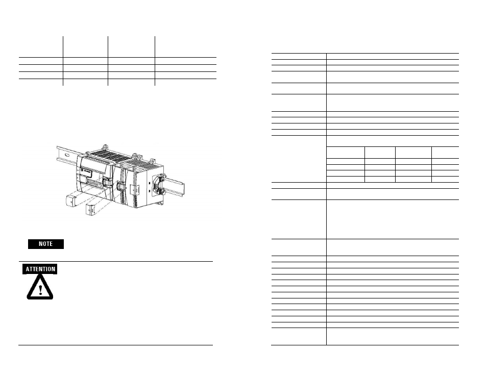
System Assembly
The expansion I/O module is attached to the controller or another I/O module by
means of a ribbon cable after mounting as shown below.
Use the pull loop on the connector to disconnect
modules.
Do not pull on the ribbon cable.
EXPLOSION HAZARD
• In Class I, Division 2 applications, the bus connector must
be fully seated and the bus connector cover must be snapped
in place.
• In Class I, Division 2 applications, all modules must be
mounted in direct contact with each other as shown on page
6. If DIN rail mounting is used, an end stop must be
installed ahead of the controller and after the last 1762 I/O
module.
MicroLogix™ Combo Analog Input/Output Module
17
Publication 0100161-01 Rev. B
Specifications
General Specifications
Specification Description
Isolation Withstand
Channel to Rack
707 VDC for 1 minute (withstand voltage) Optical & magnetic
Input Channel to
Channel
No isolation between channels other than specified in Input
voltage range and protection.
Output channel to
channel
Return lines are connected together. No isolation between
channels.
Output Channel to Input
Channel Crosstalk
The input channel(s) must maintain repeatability specification
while the output channel(s) step change from minimum to
maximum full scale, or from maximum to minimum.
Power Requirements
Internal rack +5V
30 mA maximum
Internal rack +24V
3.0W Max (125mA max at 24V)
Heat Dissipation
3.0W total Max
Maximum number of
modules on the bus
Distance rating of 6. Maximum number of modules by controller
type:
Controller
Max 5V
Bus Current
Max 24V
Bus Current
Max # of
Modules
ML1100 800
700
4
ML1200 (24pt.)
400
350
3
ML1200 (40pt.)
600
500
4
ML1400 1500
1500
7
Fusing None
Wire Size
Up to two wires of size #14-#22 AWG (solid) or #16- #22 AWG
(stranded)
Wire Type
To ensure proper operation and high immunity to electrical noise,
always use Belden 8761 (shielded, twisted pair) or equivalent wire
for voltage and current sensors or shielded, twisted pair
thermocouple extension lead wire specified by the thermocouple
manufacturer for the thermocouple type you are using. Using the
incorrect thermocouple extension wire type or not following the
correct polarity convention will cause invalid readings.
Dimensions
90 mm (height) x 87 mm (depth) x 40 mm (width)height including
mounting tabs is 110 mm. 3.54 in. (height) x 3.43 in (depth) x 1.58
in (width)height including mounting tabs is 4.33 in.
Storage Temperature
-40˚C to +85˚C (-40˚F to 185˚F)
Operating Temperature
-20˚C to 60˚C (-4˚F to +140˚F)
Operating Humidity
5% to 95% non-condensing
Vibration
Operating: 10 to 500 Hz, 5G, 0.030 in. max peak-to-peak
Shock Operating:
30G
Weight, unpackaged
0.187 kg (0.412 lb)
Weight, packaged
0.281 kg (0.619 lb)
Module Identification
Vendor I.D.
58
Product Type
10
Product Code
22
Certifications
Agency Certification
C-UL listed (under CSA C22.2 No. 142)
UL 508 listed
CE compliant for all applicable directives