Terminal block layout, Labeling the terminals – Spectrum Controls 1762sc-IF4OF4 User Manual
Page 10
MicroLogix™ Combo Analog Input/Output Module
10
Publication 0100161-01 Rev. B
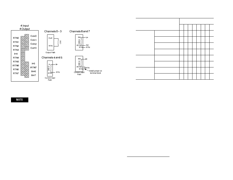
Terminal Block Layout
Grounding the cable shield at the module end only usually
provides sufficient noise immunity. However, for best cable
shield performance, earth ground the shield at both ends, using a
0.01µF capacitor at one end to block AC power ground currents,
if necessary.
Labeling the Terminals
A write-on label is provided with the module. Remove the label from the door,
mark the identification of each terminal with permanent ink, and slide the label
back into the door.
TC/Voltage
Input Path
MicroLogix™ Combo Analog Input/Output Module
15
Publication 0100161-01 Rev. B
To Select
Make these bit settings
7
6
5
4
3
2
1
0
Input Type
4 to 20 mA
0
0
0 to 20 mA
0
1
Reserved
1
0
Channel Disabled
1
1
Open Circuit
(For Module)
1
Upscale
0
Zero
1
Temperature
Scale
(For Module)
1
Deg C
0
Deg F
1
1
This is a module wide setting which is only recognized within the
configuration for Channel 4. The corresponding bit in Channel 5 is ignored.