Minimum spacing, Din rail mounting – Spectrum Controls 1762sc-IF4OF4 User Manual
Page 6
MicroLogix™ Combo Analog Input/Output Module
6
Publication 0100161-01 Rev. B
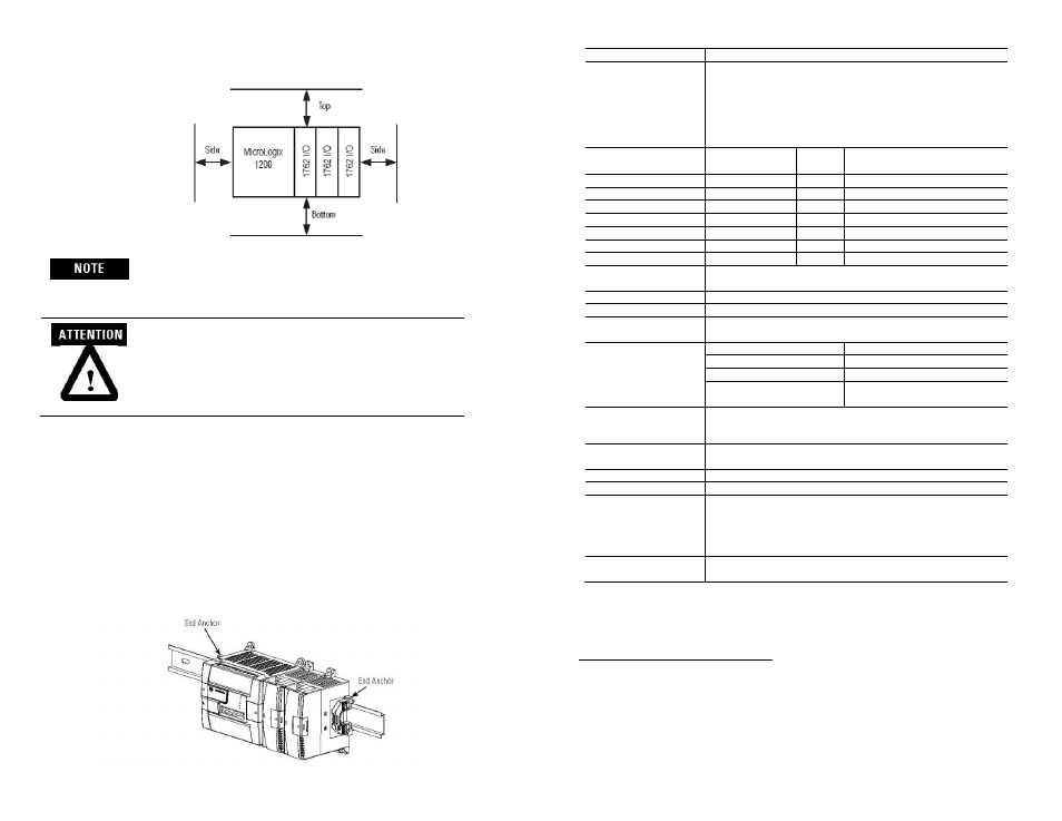
Minimum Spacing
Maintain spacing
from enclosure walls,
wireways, adjacent
equipment, etc. Allow
50.8 mm (2 in.) of
space on all sides for
adequate ventilation,
as shown
1762 expansion I/O may be mounted horizontally only.
During panel or DIN rail mounting of all devices, be sure
that all debris (metal chips, wire strands, etc.) is kept from
falling into the module. Debris that falls into the module
could cause damage when power is applied to the module.
DIN Rail Mounting
The module can be mounted using the following DIN rails: 35 x 7.5 mm (EN 50
022 - 35 x 7.5) or 35 x 15 mm (EN 50 022 - 35 x 15).
Before mounting the module on a DIN rail, close the DIN rail latch. Press the
DIN rail mounting area of the module against the DIN rail. The latch will
momentarily open and lock into place.
Use DIN rail end anchors (Allen-Bradley part number 1492-EA35 or 1492-
EAH35) for environments with vibration or shock concerns.
MicroLogix™ Combo Analog Input/Output Module
19
Publication 0100161-01 Rev. B
Specification Description
Current Inputs
System accuracy at 25° C (4 and 17 Hz filters):
± 20 uA maximum for 0-20 mA inputs
± 20 uA maximum for 4-20 mA inputs
System accuracy at -20-60°C (4 and 17 Hz filters):
± 50 uA maximum for 0-20 mA inputs
± 50 uA maximum for 4-20 mA inputs
Input Repeatability (at
25C)
4Hz Filter
17Hz
Filter
62 and 470Hz Filters typical values
2
Thermocouples)
Type J
± 0.3 °C
±0.3 °C
Not Recommended
Type K
± 0.4 °C
±0.4 °C
Not Recommended
Type N
± 0.3 °C
±0.3 °C
Not Recommended
Type E
± 0.3 °C
±0.3 °C
Not Recommended
Voltage Inputs
± 1 mV
± 2 mV
± 4 mV
Current Inputs
± 2 µA
± 2 µA
± 6 µA
Input Effective
Resolution (25°C)
3
±10V
0.48 mV
0-20mA
1 µA
Input CMRR
For 4 Hz and 17 Hz Filters: 75 dB from DC up to 10kHz with the
culprit amplitude up to the input voltage range.
Input NMRR
4 Hz Filter
74dB minimum at 50 and 60 Hz
17 Hz Filter
65dB minimum at 50 and 60 Hz
62 Hz Filter
First notch at 31Hz, typically 30dB
470 Hz Filter
First notch at 237 Hz, typically
35dB
Input Bias/Leakage
Current
±15µA steady state (±500uA peak max, <200µS duration) over
specified voltage span for input range. Applicable for voltage and TC
input configurations only.
Input Impedance -
Current
249.9 (±1%) ohms for current inputs
Input CrossTalk
70dB rejection from 0 to 10 kHz for 4 and 17 Hz filters.
Input Cable Impedance
25 ohms maximum for specified accuracy in voltage, TC modes.
Input voltage range and
protection in voltage
mode
The input voltage on any input pin must be within ±13VDC of the
output return lines for normal operation. The input lines can
withstand up to ±28VDC continuous without damage, but the
leakage bias/leakage current will increase, and input value is
undefined.
Input Protection in
current mode
Max Current input is limited due to input impedance is 42 mA max,
approximately 10.5 VDC.
2
These filters do not reject 50/ 60 Hz. Repeatability for these filters is strongly dependent
on how much 50/60Hz noise is in the system.
3
Effective resolution is based on using a 4Hz filter, the proportional counts data format,
and represents the noise free data with a steady input over time, or a statistical equivalent
of the same.