Wiring the finger-safe terminal block – Spectrum Controls 1762sc-IF4OF4 User Manual
Page 11
MicroLogix™ Combo Analog Input/Output Module
14
Publication 0100161-01 Rev. B
This table describes the channel specific configuration registers that are individually
selectable for output channels 0 through 3.
To Select
Make these bit settings
7
6
5
4
3
2
1
0
Output Type
4 to 20 mA
0
0
0
0 to 20 mA
0
0
1
-10 to 10 V
0
1
0
0 to 10 V
0
1
1
1 to 5 V
1
0
0
0 to 5 V
1
0
1
Reserved
1
1
0
Channel Disabled
1
1
1
Data Format
Scaled for PID
0
0
Engineering Units
0
1
Percent Range
1
0
Raw/Proportional Data
1
1
Unused
0 0 0
This section details the channel specific configuration registers that are individually
selectable for channels 4 and 5
To Select
Make these bit settings
7
6
5
4
3
2
1
0
Filter
Frequency
(Ignored if
Display CJC)
17 Hz
0
0
4 Hz
0
1
62 Hz
1
0
470 Hz
1
1
Data Format
Engineering Units X1
0
0
Engineering Units X10
0
1
Raw/Proportional
Data
1
0
Scaled for PID
1
1
MicroLogix™ Combo Analog Input/Output Module
11
Publication 0100161-01 Rev. B
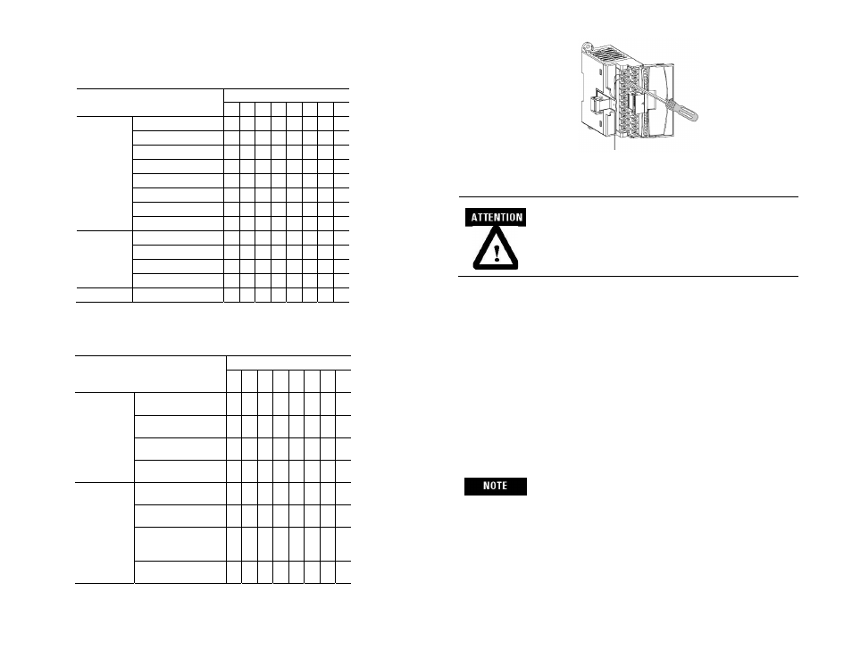
Wiring the Finger-Safe Terminal Block
Be careful when stripping wires. Wire fragments that fall into
a module could cause damage when power is applied. Once
wiring is complete, ensure the module is free of all metal
fragments.
When wiring the terminal block, keep the finger-safe cover in place.
1. Route the wire under the terminal pressure plate. You can use the stripped
end of the wire or a spade lug. The terminals will accept a 6.35 mm (0.25
in.) spade lug.
2. Tighten the terminal screw making sure the pressure plate secures the
wire. Recommended torque when tightening terminal screws is 0.904 Nm
(8 in-lbs).
3. After wiring is complete, remove the debris shield.
If you need to remove the finger-safe cover, insert a screw
driver into one of the square wiring holes and gently pry the
cover off. If you wire the terminal block with the finger-safe
cover removed, you will not be able to put it back on the
terminal block because the wires will be in the way