Wire size and terminal screw torque, Addressing, Input data file – Spectrum Controls 1762sc-IF4OF4 User Manual
Page 12: Configuration data file, Output data file
MicroLogix™ Combo Analog Input/Output Module
12
Publication 0100161-01 Rev. B
Wire Size and Terminal Screw Torque
Each terminal accepts up to two wires with the following restrictions:
Wire Type
Wire Size
Terminal Screw
Torque
Solid
Cu-90°C (194°F)
#14 to #22 AWG
0.904 Nm (8 in-lbs)
Stranded Cu-90°C (194°F)
#16 to #22 AWG
0.904 Nm (8 in-lbs)
I/O Memory Mapping
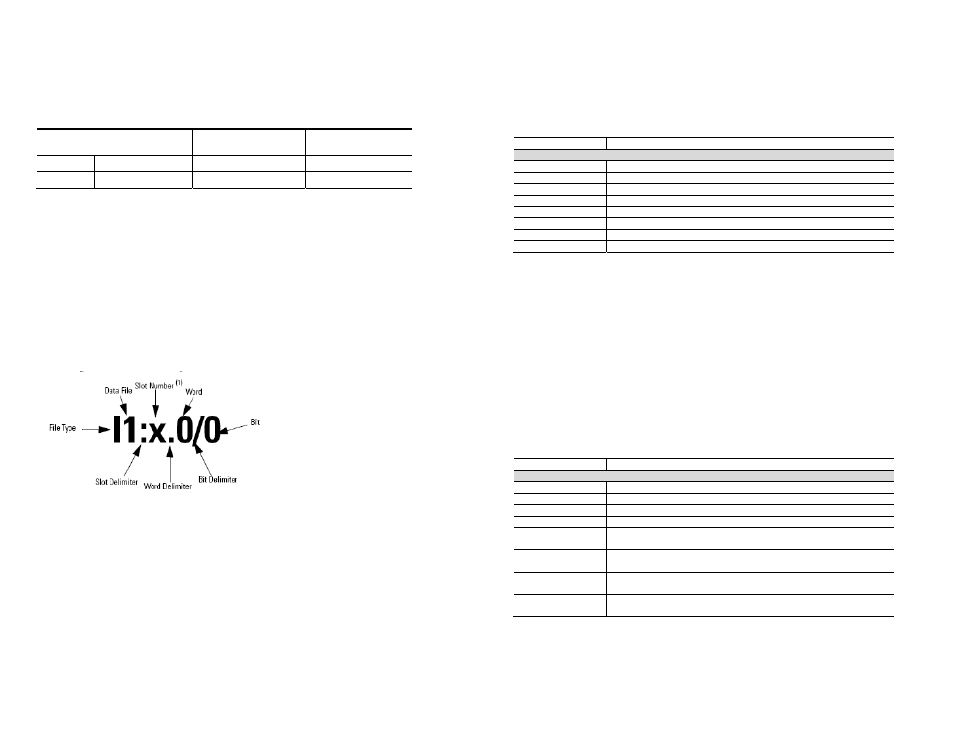
Addressing
The addressing scheme for 1762 Expansion I/O is shown below.
(1)
I/O located on the controller (embedded I/O) is slot 0. I/O added to the controller (expansion I/O) begins
with slot 1.
MicroLogix™ Combo Analog Input/Output Module
13
Publication 0100161-01 Rev. B
Input Data File
For each module, slot x, words 0 through 3 contain module status information.
Words 4 through 7 contain analog input data for channels 4 through 7 respectively.
The table below shows the layout for the input data file.
Input Data File
Register Function
Input File (Module Data)
I:e.0
General Status Word 0
I:e.1
Output Status Word 1
I:e.2
Input Status Word 2
I:e.3
Raw CJC Temperature
I:e.4
Channel 4 Data Word
I:e.5
Channel 5 Data Word
I:e.6
Channel 6 Data Word
I:e.7
Channel 7 Data Word
Configuration Data File
The configuration data file is not used. Instead the output data file is used to
configure the module.
Output Data File
The output data file is used to configure the 1762sc-IF4OF4 module. Take care
when making changes to the configuration (i.e. output data file) while in run mode.
Illegal configurations could fault the controller.
The table below shows the layout for the output data file. Note that words 4
through 7 are used to define the module configuration.
Output Data File
Register Function
Output File (Used for Module Configuration)
O:e.0
Channel 0 Data Word
O:e.1
Channel 1 Data Word
O:e.2
Channel 2 Data Word
O:e.3
Channel 3 Data Word
O:e.4
Low byte: Channel 0 Configuration Register (Output)
High byte: Channel 1 Configuration Register (Output)
O:e.5
Low byte: Channel 2 Configuration Register (Output)
High byte: Channel 3 Configuration Register (Output)
O:e.6
Low byte: Channel 4 Configuration Register (Input)
High byte: Channel 5 Configuration Register (Input)
O:e.7
Low byte: Channel 6 Configuration Register (Input)
High byte: Channel 7 Configuration Register (Input)