Spectrum Controls 1762sc-IF8U User Manual
Page 9
Chapter 1: Module Overview
1-3
User's Manual Pub. 0300243‐02 Rev. B
Section 1.5
Hardware
Features
Channels are wired as differential inputs with the exception of RTD and resistance type
inputs. One cold junction compensation (CJC) sensor comes installed on the terminal
block to enable accurate readings when using thermocouple input types. The CJC sensor
compensates for offset voltages introduced into the input signal as a result of the cold-
junction where the thermocouple wires come into contact with the terminal block.
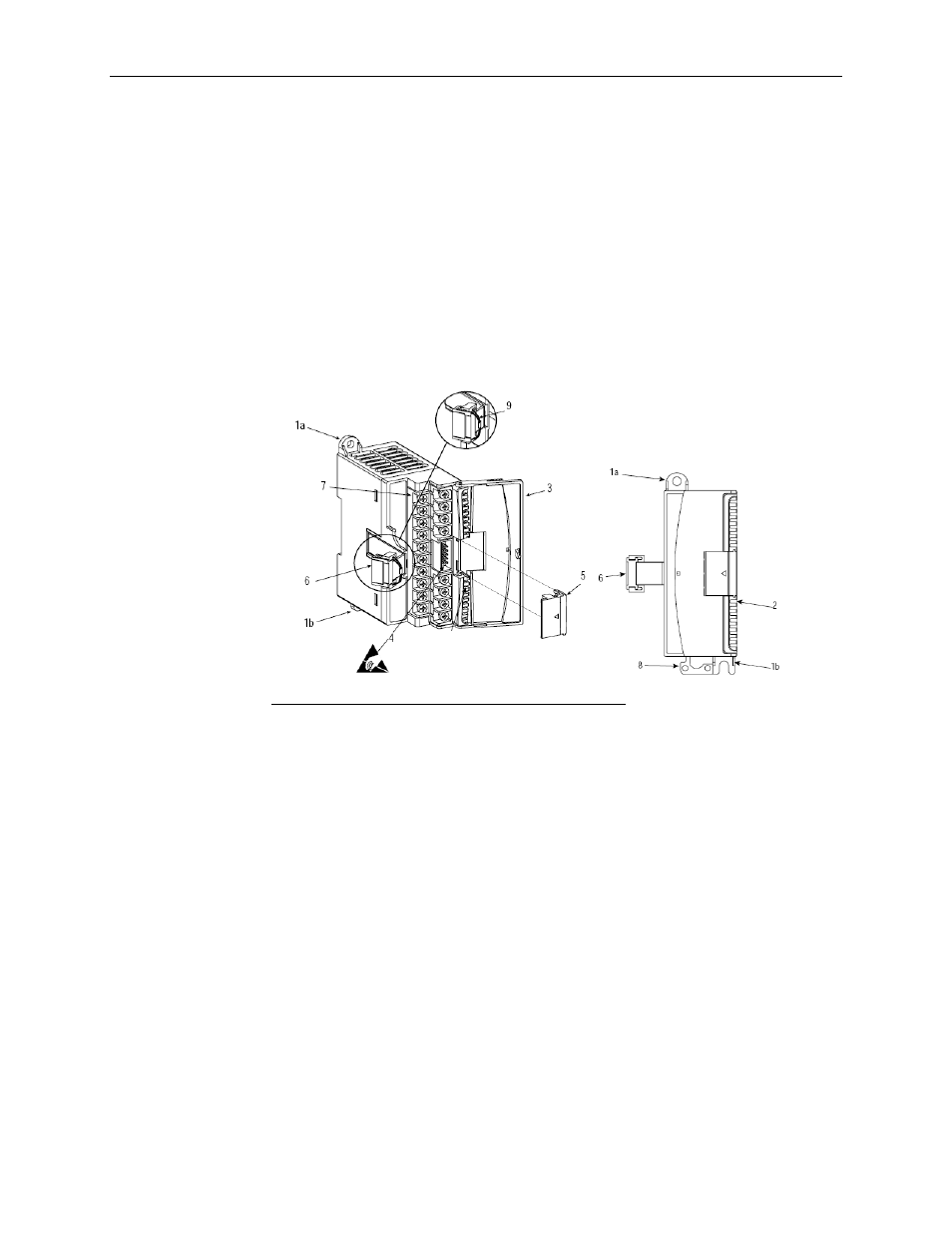
Module configuration is done via the controller’s programming software and hardware
dip switch settings. The module configuration is stored in the memory of the controller.
Refer to your controller’s user manual for more information. The illustration below
shows the module’s hardware features.
Item Description
1a
Upper panel mounting tab
1b
Lower panel mounting tab
2 Power
diagnostic
LED
3
Module door with terminal identification label
4
Bus connector (male)
5 Bus
connector
cover
6
Flat ribbon cable with bus connector (female)
7 Terminal
block
8 DIN
rail
latch
9 Pull
loop
1.5.1 LED Indicator
The 1762 universal module uses a single green LED to show operational status of the
module. When startup is completed and all internal tests have passed, the LED will
illuminate solid. If the LED remains off, there is an error with the module.
Figure 1-1