Spectrum Controls 1762sc-IF8U User Manual
Page 23
Chapter 3: Configuring the 1762sc-IF8u for RSLogix 500
3-3
User's Manual Pub. 0300243‐02 Rev. B
5.) Repeat steps 1 through 4 for additional modules.
Section 3.4
Module
Configuration
The IF8u is configured using the output data table within RSLogix 500 and dip-switch
settings located on the circuit board.
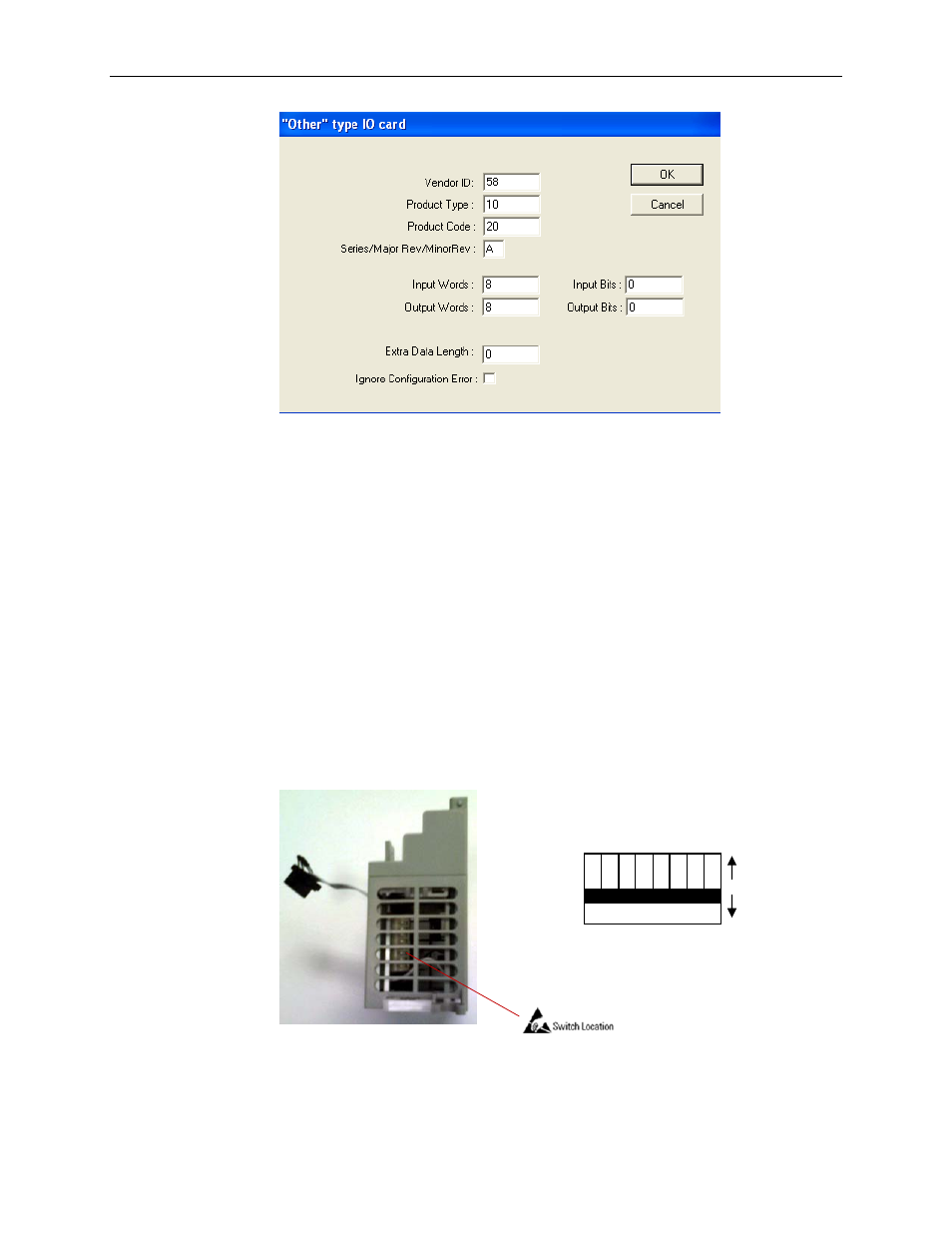
3.4.1 Dip-Switch Configuration
There are 8 dip-switches located on the circuit board of the IF8u module. The switches
are used to configure the correct input path (i.e. Current or Non-Current). Refer to the
diagram below for proper dip-switch settings.
3.4.2 Output Data File (Configuration Data)
The output data file is used to configure the advanced settings of the module including
input type, data format, filter settings, etc. Use the addressing scheme below to locate the
1 2 3 4 5 6 7 8
Non-Current
Current
Channel #
Figure 3-2 (Dip-Switch Settings)