2 wiring the finger-safe terminal block – Spectrum Controls 1762sc-IF8U User Manual
Page 19
Chapter 2: Installation and Wiring
2-9
User's Manual Pub. 0300243‐02 Rev. B
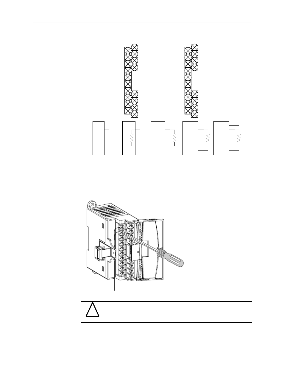
2.6.2 Wiring the Finger-Safe Terminal Block
Figure 2-6
!
Attention
Be careful when stripping wires. Wire fragments that fall into a module
could cause damage when power is applied. Once wiring is complete,
ensure the module is free of all metal fragments.
IN +0
IN +1
IN +2
IN +3
IN +4
IN +5
IN +6
IN +7
IN -0
IN -1
IN -2
IN -3
IN -4
IN -6
IN -7
CJC +
CJC -
EXC 0
Sense 0+
EXC 2
Sense 2+
EXC 4
Sense 4+
EXC 6
Sense 6+
Sense 0-
RTN 0
Sense 2-
RTN 2
Sense 4-
RTN 4
Sense 6-
RTN 6
CJC +
CJC -
Or
V+
V-
Voltage Input
Path (DIP
switch open)
Current Input
Path (DIP
switch closed)
i+
i-
24
9
?
3-wire
Resistance /
RTD Input Path
2-wire
Resistance /
RTD Input Path
4-wire
Resistance /
RTD Input Path
EXC
RTN
EXC
RTN
Sense-
Sense+
EXC
RTN
Sense-
IN+
IN-
IN+
IN-
Ω
IN -5
Figure 2-5 (Wiring Diagram)