Spectrum Controls 1762sc-IF8U User Manual
Page 24
3-4
MicroLogix™ 1200 IO Universal Input Module
User's Manual Pub. 0300243‐02 Rev. B
8 output words needed to configure the module.
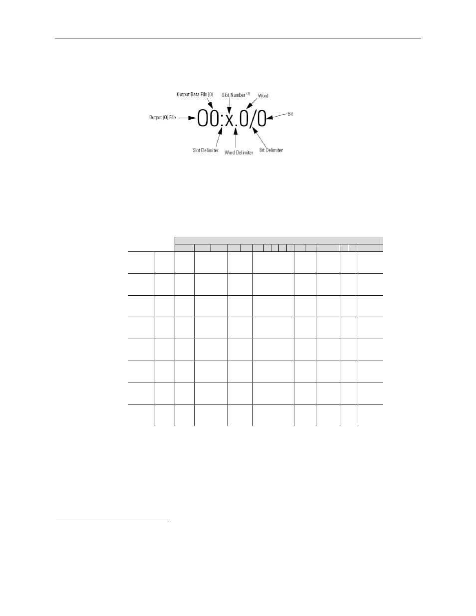
(1)
I
/O located on the controller (embedded I/O) is slot 0. I/O added to the controller (expansion I/O) begins
with slot 1.
The table below shows the general layout for the 8 output words used for configuration.
Table 3-1 (Output File)
Channel Word
Bits
15
14
13
12
11 10 9 8 7 6
5
4
3
2 1
0
Ch0 0
Temp
Units
CJC
&
Lead Comp
Data
Format
4
Input Type
Open
Circuit
CJC
Display
Filter
Enable
Channel
Ch1 1
Temp
Units
CJC
&
Lead Comp
Data
Format
4
Input Type
Open
Circuit
CJC
Display
Filter
Enable
Channel
Ch2 2
Temp
Units
CJC
&
Lead Comp
Data
Format
4
Input Type
Open
Circuit
CJC
Display
Filter
Enable
Channel
Ch3 3
Temp
Units
CJC
&
Lead Comp
Data
Format
4
Input Type
Open
Circuit
CJC
Display
Filter
Enable
Channel
Ch4 4
Temp
Units
CJC
&
Lead Comp
Data
Format
4
Input Type
Open
Circuit
CJC
Display
Filter
Enable
Channel
Ch5 5
Temp
Units
CJC
&
Lead Comp
Data
Format
4
Input Type
Open
Circuit
CJC
Display
Filter
Enable
Channel
Ch6 6
Temp
Units
CJC
&
Lead Comp
Data
Format
4
Input Type
Open
Circuit
CJC
Display
Filter
Enable
Channel
Ch7 7
Temp
Units
CJC
&
Lead Comp
Data
Format
4
Input Type
Open
Circuit
CJC
Display
Filter
Enable
Channel
Table 3-2 on the following page lists the possible configuration settings for each channel.
4
Refer Table 3-3 for data ranges.