Front panel controls, L (low) band – Speck Electronics ASC User Manual
Page 16
12
This control is used to adjust the
input sensitivity between -12dB and
+6dB relative to the level that is
present at the input connector. The
center detented position is “0” unity
gain. Under normal operation with
a balanced input and balanced
output, this control can be set to the
“0” position. In cases when the
ASC is interfaced to an unbalanced
device, a 6dB loss may occur. The
gain control can be set to +6dB to
compensate for this loss of signal.
This switch is used to enable or disable the equalization circuit. In the
“out” position all equalizer bands are bypassed. When in the bypass
position, the active balanced input stage, the gain control, the active
balanced output stage, and the optional transformer remains operational.
This allows the levels to match when comparing the equalized signal to
the unequalized signal, even when the gain control has been set higher
or lower than 0 db.
When this switch is depressed, the equalizer is enabled.
This dual colored LED will illuminate red indicating that the ASC is
powered and active. It also indicates that the equalizer is in the “bypass”
mode. When the switch is depressed, this LED will change from red to
green indicating that the equalizer is enabled.
The low frequency sweep control is used in conjunction with the low
boost/cut control and provides
continuous adjustment of the center
frequency from 20Hz (fully
counterclockwise) to 150Hz (fully
clockwise).
Bandwidth (Q)
The bandwidth for the selected
frequency of the low band is
automatically adjusted with the
selection of the frequency sweep
control. The 20Hz setting on the
sweep control will result in a narrow
bandwidth of approximately .25
octave (Q=4).
As the frequency sweep control is adjusted to its highest setting
(150Hz), the bandwidth widens to approximately 1.6 octaves (Q=.6).
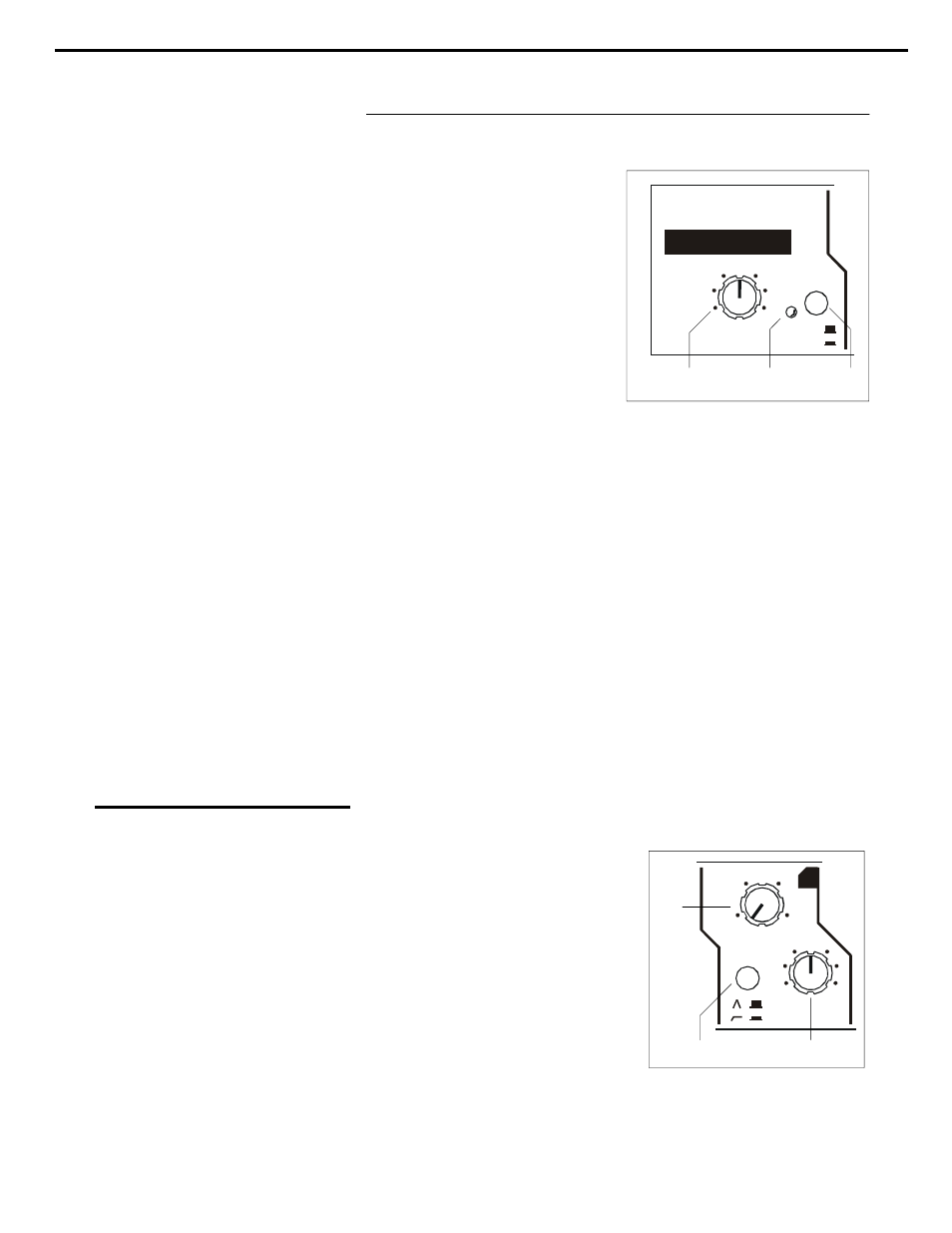
FRONT PANEL CONTROLS
1. Gain Control
2. Equalizer bypass switch
3. Power/Bypass LED
L (LOW) BAND
4. Low frequency sweep
Chapter 3 Operation Section
0
0
0
0
0
0
0
0
0
0
0
0
0
0
0
0
0
0
0
6
6
6
6
+
+
+
BYPASS
BYPASS
BYPASS
BYPASS
IN
IN
IN
IN
IN
IN
G i
Gain
Gain
Gain
Gain
k
k
speck
speck
speck
speck
speck
speck
speck
speck
p
p
l
i
l
t
i
l
t
i
electronics
electronics
electronics
electronics
electronics
electronics
electronics
SC
ASC
ASC
ASC
ASC
ASC
ASC
ASC
ASC
ASC
M d l
Model
Model
Model
Model
Model
Model
Model
Model
12
12
12
12
_
1
3
2
20
30
55
90
150
0
15
+
15
_
si
L
5
6
4